Table 5-13 Configuration principles of the SLPU (1)
Board Optional/
Mandatory
Maximum
Quantity
Slot Configuration
Restriction
UELP Optional 4 Slots 0 to 3 The priorities of
the slots in
configuration
are as follows in
descending
order: slot 2, slot
0, slot 1, and slot
3.
UFLP
Optional 1 Slot 3 If both the
UELP and
UFLP are
configured, the
UFLP is
installed in a slot
with a higher
priority than the
UELP.
When serving as a monitoring signal protection unit for not more than 16 dry contacts, the SLPU
is an optional component, and it is integrated with two USLP2s and installed in the 1 U space
at the bottom of the BBU. Table 5-14 lists the configuration principles of the SLPU.
Table 5-14 Configuration principles of the SLPU (2)
Board
Optional/
Mandatory
Quantity Slot Configuration
Restriction
USLP2 Optional 2 Slots 2 and 3 -
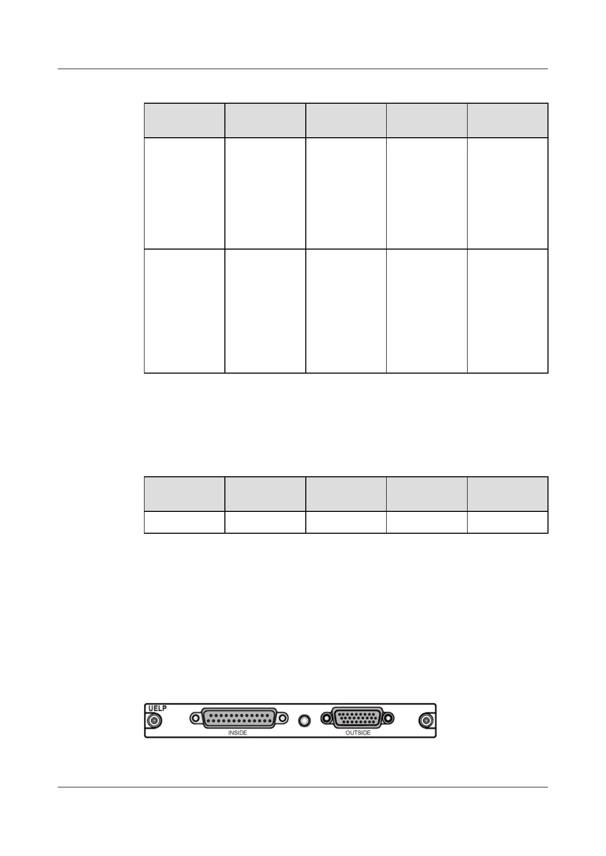
5.8.3 UELP
Each Universal E1/T1 Lightning Protection Unit (UELP) provides surge protection for four
paths of E1/T1 signals.
Panel
Figure 5-16 shows the panel of the UELP.
Figure 5-16 UELP panel
5 Auxiliary Devices of the BBU3900
BBU3900
Hardware Description
5-20 Huawei Proprietary and Confidential
Copyright © Huawei Technologies Co., Ltd.
Issue 11 (2010-11-10)

 Loading...


