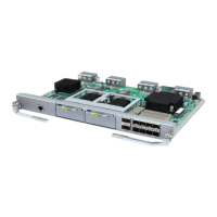
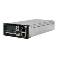
Figure 3-13 Panel of the UPEUB
(1) Power switch of the BBU
Functions
The UPEU performs the following functions:
l Converts -48 V DC or +24 V DC power to +12 V DC power that is applicable to the boards
l Provides two ports for two RS485 inputs and two ports for eight Boolean signals
l Provides reverse connection protection for power cable connectors
l If two UPEUs are configured, two power inputs are required. The UPEU in slot 19 works
in active mode, and the UPEU in slot 18 works in standby mode
LEDs
The UPEU has one LED that indicates the operating status of the board. Table 3-13 describes
the LED and its status.
Table 3-13 LED on the UPEU and its status
Label
Color Status Description
RUN Green On The UPEU is
operational.
Off Input power is
unavailable or the
board is faulty.
Ports
The UPEU provides two RS485 ports and two ports for eight Boolean signals. When configured
in different slots, the ports on the UPEU have different functions. Figure 3-14 shows the slots
in the BBU.
Figure 3-14 Slots in the BBU
BBU3900
Hardware Description 3 BBU3900 Equipment
Issue 11 (2010-11-10) Huawei Proprietary and Confidential
Copyright © Huawei Technologies Co., Ltd.
3-15
 Loading...

