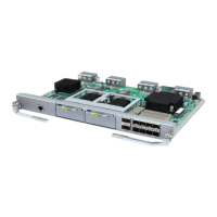
Table 3-20 Ports on the panel of the UTRP3 and UTRP4 supporting eight E1s/T1s
Label Port Type Quantity Connector Type
E1/T1 E1/T1 port 2 DB26 connector
Table 3-21 describes the port of the UTRP6 supporting one STM-1.
Table 3-21 Port of the UTRP6 supporting one STM-1
Label Port Type Quantity Connector Type
STM-1/OC-3 STM-1/OC-3 port 1 SFP connector
Table 3-22 describes the ports of the UTRP9 supporting four electrical ports.
Table 3-22 Ports of the UTRP9 supporting four electrical ports
Label Port Type Quantity Connector Type
FE/GE0 to FE/GE3 FE/GE electrical port 4 RJ-45 connector
DIP Switches
There is no DIP switch on the UTRP2, UTRP6, and UTRP9.
The UTRP3 or UTRP4 has three DIP switches numbered from SW1 to SW3. SW1 and SW2 are
used to set the grounding status of the eight E1s. SW3 is used to set matched impedance for the
eight E1s. Figure 3-20 shows the DIP switch on the UTRP3 or UTRP4.
Figure 3-20 DIP switch on the UTRP3 or UTRP4
Table 3-23, Table 3-24, and Table 3-25 describe how to set the DIP switches on the UTRP.
BBU3900
Hardware Description 3 BBU3900 Equipment
Issue 11 (2010-11-10) Huawei Proprietary and Confidential
Copyright © Huawei Technologies Co., Ltd.
3-21
 Loading...

