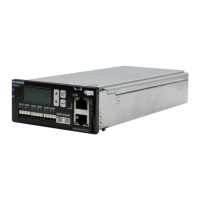
Figure 5-9 DIP switches on the PMU
Table 5-9 describes the settings of the DIP switches on the PMU.
Table 5-9 Settings of the DIP switches on the PMU
No.
Function Operation
1~5 Defines the communication
address of the PMU
(1) Switches 1 to 5
correspond to bits 0 to 4. ON:
1, OFF: 0
For example: to set the
address of PMU to 3, set
switches 3 to 5 as OFF.
(2) Default setting before
delivery:
1 (BIT0), ON
2 (BIT1), ON
3 (BIT2), OFF
4 (BIT3), OFF
5 (BIT4), OFF
5 Auxiliary Devices of the BBU3900
BBU3900
Hardware Description
5-14 Huawei Proprietary and Confidential
Copyright © Huawei Technologies Co., Ltd.
Issue 11 (2010-11-10)
 Loading...

