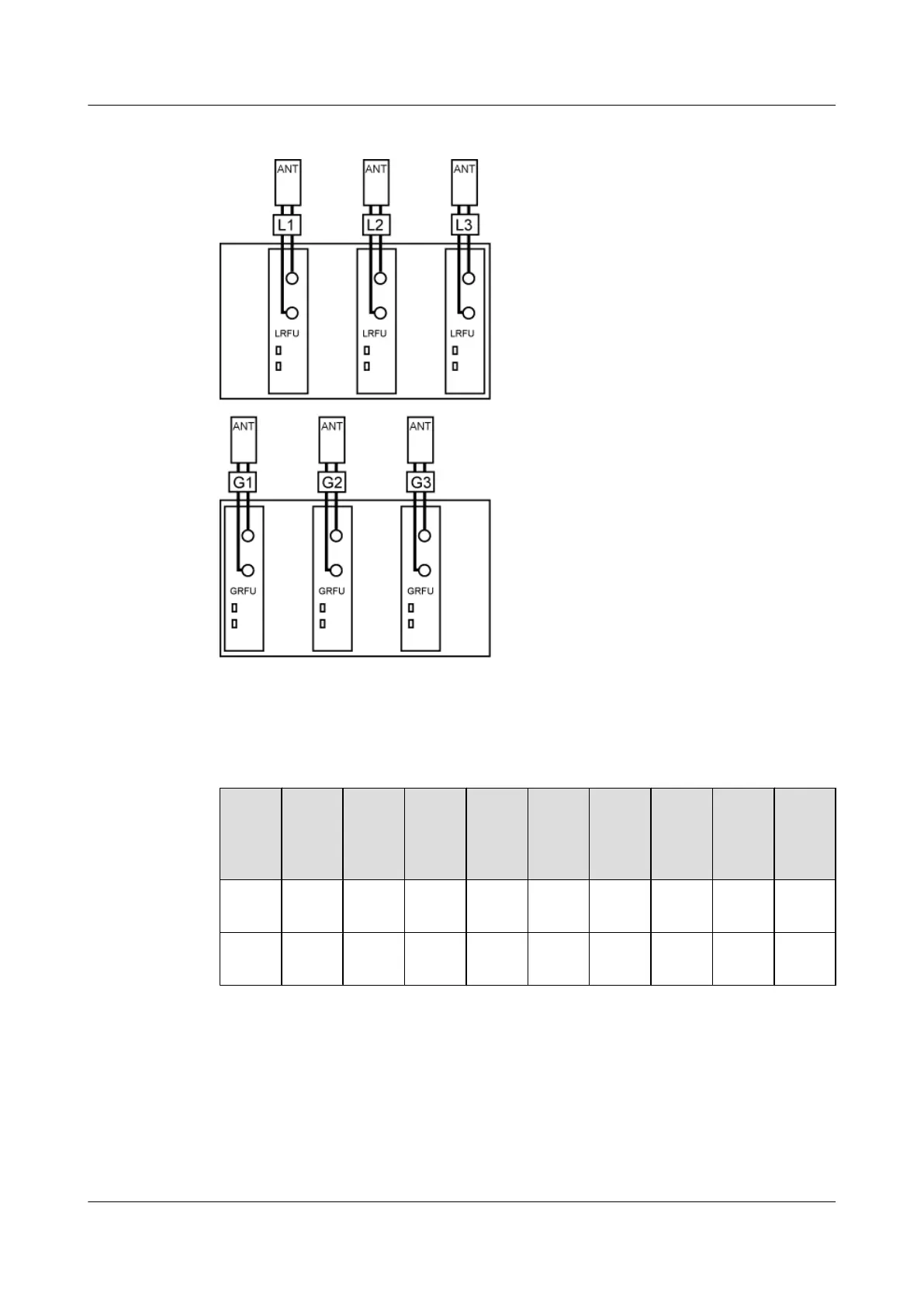
Figure 3-56 3GRFU+LRFU 3 x 20 MHz
Scenario 5: A tri-band base station, with the configuration of MRFUs, GRFUs, and LRFUs
Table 3-41 Slot assignment for MRFUs, GRFUs, and LRFUs in a tri-band base station
Secto
r
Num
ber
M1 M2 M3 G7 G8 G9 L1 L2 L3
Cabin
et 1
Slot 0
or 1
Slot 2
or 3
Slot 4
or 5
- - - - - -
Cabin
et 2
- - - Slot 0 Slot 2 Slot 4 Slot 1 Slot 3 Slot 5
3 BTS3900 Hardware Configuration
BTS3900
Hardware Description
3-60 Huawei Proprietary and Confidential
Copyright © Huawei Technologies Co., Ltd.
Issue 04 (2011-02-15)

 Loading...