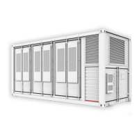
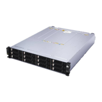
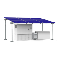
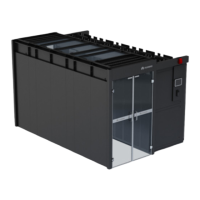
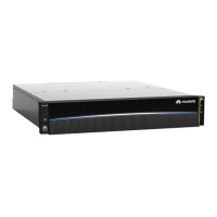
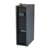
Figure 1-4 SACU+ESS FE star+PCS FE ring topology (the device in the dotted box
is optional)
Typical Scenario 3: SACU+ESS Fiber Ring+PCS FE Ring Topology
In this scenario, the SmartACU2000D-D-00 is congured, the SmartModule needs
to be congured in the SACU, and the customer needs to prepare one switch
(quantity of 10M/100M auto-sensing Ethernet ports ≥ 5). The SACU
communicates with the rst ESS through FE, and ESSs communicate with each
other through SFP optical ber cascading. In the ESS ber ring topology, a single
ber ring network supports a maximum of 15 ESSs.
Commercial and Industrial Microgrid Energy Storage
Solution
Quick Guide (With Third-Party Microgrid Central
Controller) 1 Solution Introduction
Issue 04 (2023-12-18) Copyright © Huawei Digital Power Technologies Co., Ltd. 11

 Loading...
