(as ③ in Figure 5-2). It is not recommended that the USB dongle be placed in the middle
of the PCB (as ⑧ and ⑨ in Figure 5-4).
3. The USB socket must be properly grounded to the PCB to ensure the optimal antenna
performance. It is not recommended that the PCB extend to the side of the USB dongle.
If this is required (as ② in Figure 5-2), reserve a minimum distance of 5 mm between the
USB dongle and the PCB.
4. Ensure that the USB dongle is in an open area without any other metals shielding around
(such as an earpiece or loudspeaker), except for cases of recommended layouts. If metals
cannot be avoided, a distance larger than 2 cm is required between the USB dongle and
the metal.
5. If there are other antennas in auxiliary devices, the antennas must keep a distance from
the USB dongle to avoid coupling.
6. If the diversity antenna (as ④ in Figure 5-2) is in one side of the USB dongle, the
clearance opening should be faced outwards (as shown in Figure 5-2) to ensure the
optimal antenna performance.
7. In order to minimize devices' impact to the USB dongle, corollary equipment must be
filtered or shielded
8. Do not place any components that adversely affect the antenna performance on the top of
the USB dongle, especially of the main antenna (as ⑤ in Figure 5-2). The antenna
performance will decrease by at least 1.5 dB if any adverse effect occurs.
9. It do not place any metal components around the antenna. Reference Figure 5-3.
Follow the preceding requirements to ensure the optimal MS2131 performance. If any
discrepancy exists, the MS2131 may fail to connect to the network or provide data, voice, or
SMS services.
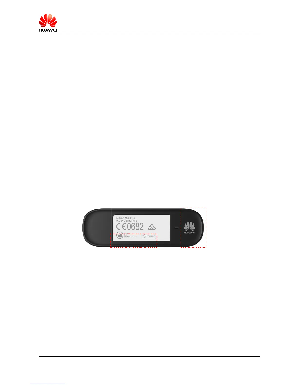
Figure 5-1 MS2131 antenna area
Main
antenna
Diversity antenna