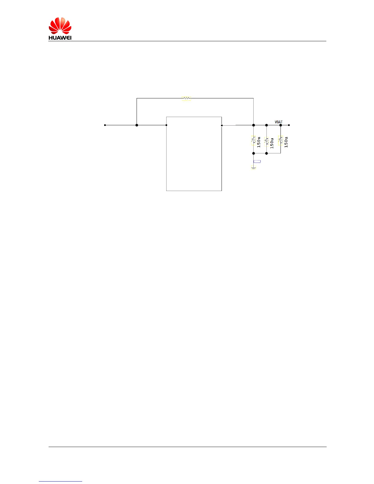
switch and disconnect the power to the MS2131 when exceptions occur. The DC impedance
of the current limiting circuit or switching diode must be less than 50 mΩ. To avoid an
oversize impedance, reserve space for a 0 Ω resistor for compatible purpose.
Figure 7-5 Recommended power structure
7.6.2 Derating Requirements
It is recommended that an 85% derating capacity be provided for the external power supply
voltage and current. If a DC/DC converter or LDO is used, ensure its derating capacity and
transient conductivity.
7.6.3 Peripheral Power Supply Design Rules
The peripheral power supply design rules for the MS2131 are described as follows:
1. The power cable routing path must be as wide as possible to bear currents larger than 2
A during transmission in GSM mode.
2. A large-capacity capacitor (at least 300 uF) must be placed near the USB port to prevent
its voltage from dropping lower than 3.5 V. Energy storage capacitors used for must be
placed near the MS2131 as much as possible to ensure optimal discharge performance of
the capacitors.
3. Overvoltage and anti-reversion diodes must be connected to external power supply
connectors to protect the power circuits when exceptions occur.
4. If the host supplies power to the MS2131 over a DC/DC converter, the converter must be
able to bear the 2 A transient current.
5. The USB power cable voltage fluctuates in GSM mode. Therefore, do not route sensitive
signal cables near the USB power cable.