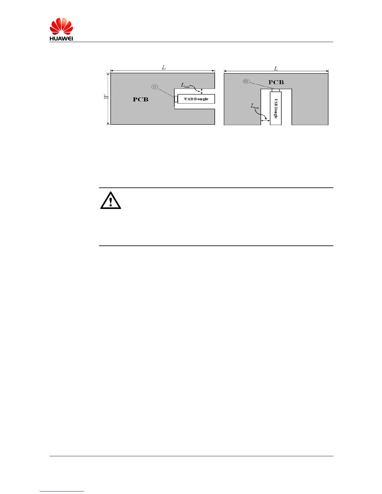
Layout 1: The USB dongle is embedded in the middle of the shorter edge.
Layout 2: The USB dongle is embedded in the middle of the longer edge.
Figure 5-4 shows two incorrect layouts with the USB dongle embedded in the middle of the
PCB. The omni-directivity of the antenna deteriorates and the efficiency decreases due to the
closed space where the antennas are.
Strictly follow the antenna layout requirements and the stacking requirements specified in
section 6.3.2 "MS2131 Peripheral Staking Requirements
" when designing the system. If you
fail to follow the requirements, the TRP and TIS specifications of the MS2131 will deteriorate,
and exceptions, such as network access failures and call failures, will occur.
5.5 Antenna Test Environment
The tests of antenna efficiency, gain, radiation pattern, and TRP and TIS specifications can be
performed in a microwave testing chamber. The following describes the test items in detail:
Passive tests:
− Antenna efficiency
− Antenna gain
− Antenna radiation pattern
− Envelope correlation coeffic ient
Active tests:
− TRP: GSM and WCDMATIS: GSM and WCDMA