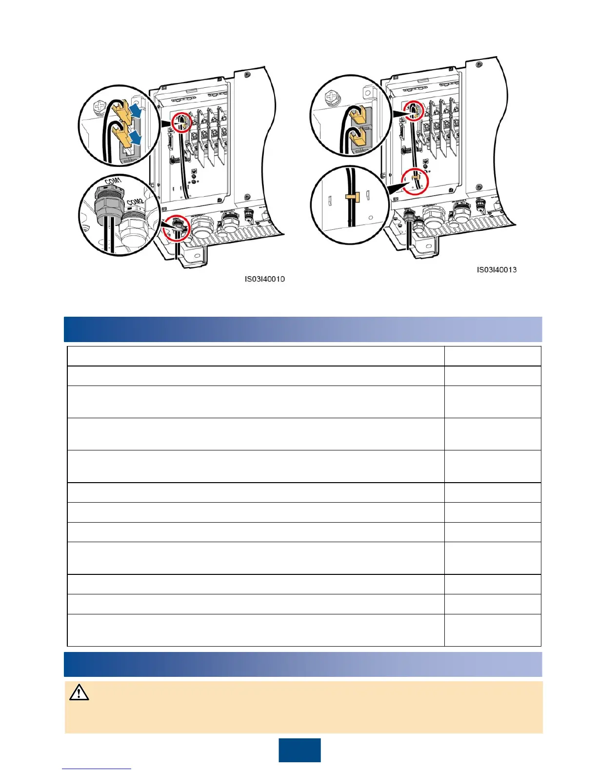
5. Insert the RJ45 connector into the FE network
port in the maintenance compartment of the
SUN2000.
6. Bind the communications cables.
7. Use a torque wrench with an open end of 33 mm to tighten the locking cap to a torque of 7.5 N·m,
and seal the waterproof connector.
15
5
Verifying the Installation
The SUN2000 is installed correctly and securely.
The DC switches and downstream AC output switch are OFF.
Ground cables are connected correctly and securely, without open circuits
or short circuits.
4. AC output power cables are connected correctly and securely, without open
circuits or short circuits.
DC input power cables are connected correctly and securely, without open
circuits or short circuits.
The communications cables are connected correctly and securely.
All the connectors in use at the bottom of the enclosure are sealed.
The AC terminal cover is reinstalled.
The maintenance compartment door is closed and the door screws are
tightened.
The idle DC input terminals are sealed.
The idle USB port is plugged with a waterproof plug.
Idle AC OUTPUT and COM connectors are plugged and the locking caps
are tightened.
▢ No ▢ N/A ▢
6
Powering On the System
Before turning on the AC switch between the SUN2000 and the power grid, use a multimeter to
check that the AC voltage is within the specified range.

 Loading...