2.2 Appearance
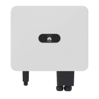
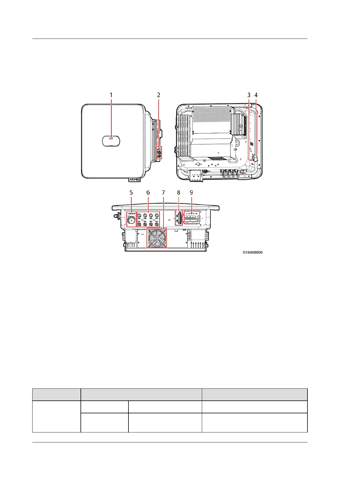
Figure 2-4 Appearance
(1) LED indicators (2) Ground screws
(3) DC switch locking screw hole
[1]
(4) DC switch (DC SWITCH)
(5) Smart Dongle port (4G/WLAN-FE) (6) DC input terminals (PV1–PV4)
(7) Fan (8) Communication port (COM)
(9) AC output ports (AC)
Note [1]: For models used in Australia, the DC switch locking screw needs to be
installed according to the local standard to secure the DC switch (DC SWITCH)
and prevent incorrect startup. The DC switch locking screw is delivered with the
device.
Table 2-2 LED indicator description
Category
Status Meaning
Running
indication
LED1 LED2 N/A
Steady green Steady green The SUN2000 is operating in grid-
tied mode.
SUN2000-(12KTL-25KTL)-M5 Series
User Manual 2 Overview
Issue 03 (2023-02-15) Copyright © Huawei Digital Power Technologies Co., Ltd. 16
 Loading...