Incremental Encoder FG 40
FG40_MANUAL-en_R12(2018-10-31)ID74490.doc
4. Align the encoder shaft (5) to the (motor) shaft and insert into the coupling hub.
NOTES!
Use shims (19) to achieve the correct vertical alignment to the base plate (20).
Observe information in Chapter 5.7about mounting errors and max. permissible
mounting tolerances!
5. Fasten encoder foot with 4 M6 hexagon head screws (18).
6. Secure the coupling hub on the encoder shaft with the grub screw or cheese head screw (11)
(depending on the coupling type).
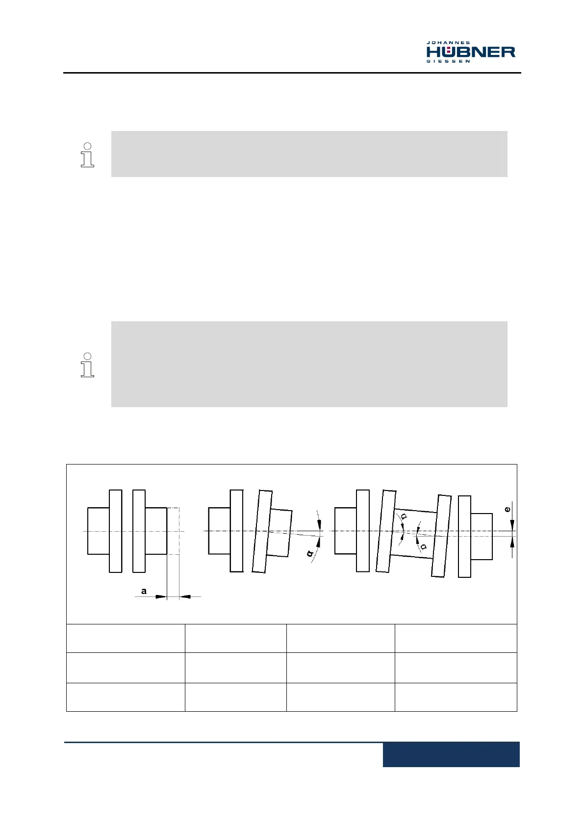
5.7 Mounting tolerances for construction type B5 and B35
NOTES!
Angle misalignment and parallel displacement between the (motor) shaft and the
encoder shaft are mounting errors and should be kept as small as possible.
Mounting errors
- Cause radial forces to act on the encoder shaft.
- Reduce the service life of the bearings and the coupling.
- Degrade the quality of the signals (harmonic content).
Mounting tolerances for our zero-backlash, torsion-resistant couplings HK5 and HKD5:
 Loading...