Incremental Encoder FG 40
FG40_MANUAL-en_R12(2018-10-31)ID74490.doc
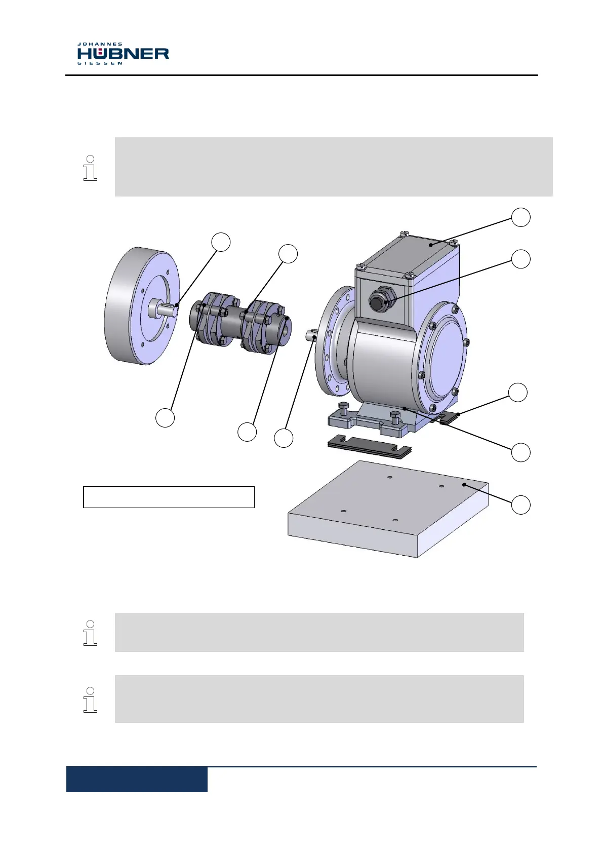
5.6 Mounting B35 type (flange and foot) incremental encoders
NOTES!
B35 type encoders can be attached by means of a flange (B5, please refer to Chapter 5.5) or
foot (B3):
For a mounting example please refer to dimension drawing HM 09 M 102 240a (Chapter 11.2).
1. Lightly grease the (motor) shaft (1).
2. Fit coupling (2) onto (motor) shaft.
NOTES!
You must be able to mount the coupling without force. Ream out the bores of used
couplings, if necessary!
NOTES!
We recommend our zero-backlash, torsion-resistant double-joint coupling HKD5 to
attach B35 type encoders. Please refer to the catalogue Torsion Resistant Couplings for
Encoders.
3. Secure the coupling hub on the (motor) shaft with a grub screw or cheese head screw (10)
(depending on the coupling type).
Figure 2: FG 40 construction type B35
 Loading...