Incremental Encoder FG 40
FG40_MANUAL-en_R12(2018-10-31)ID74490.doc
5.8 Attaching additional devices
NOTES!
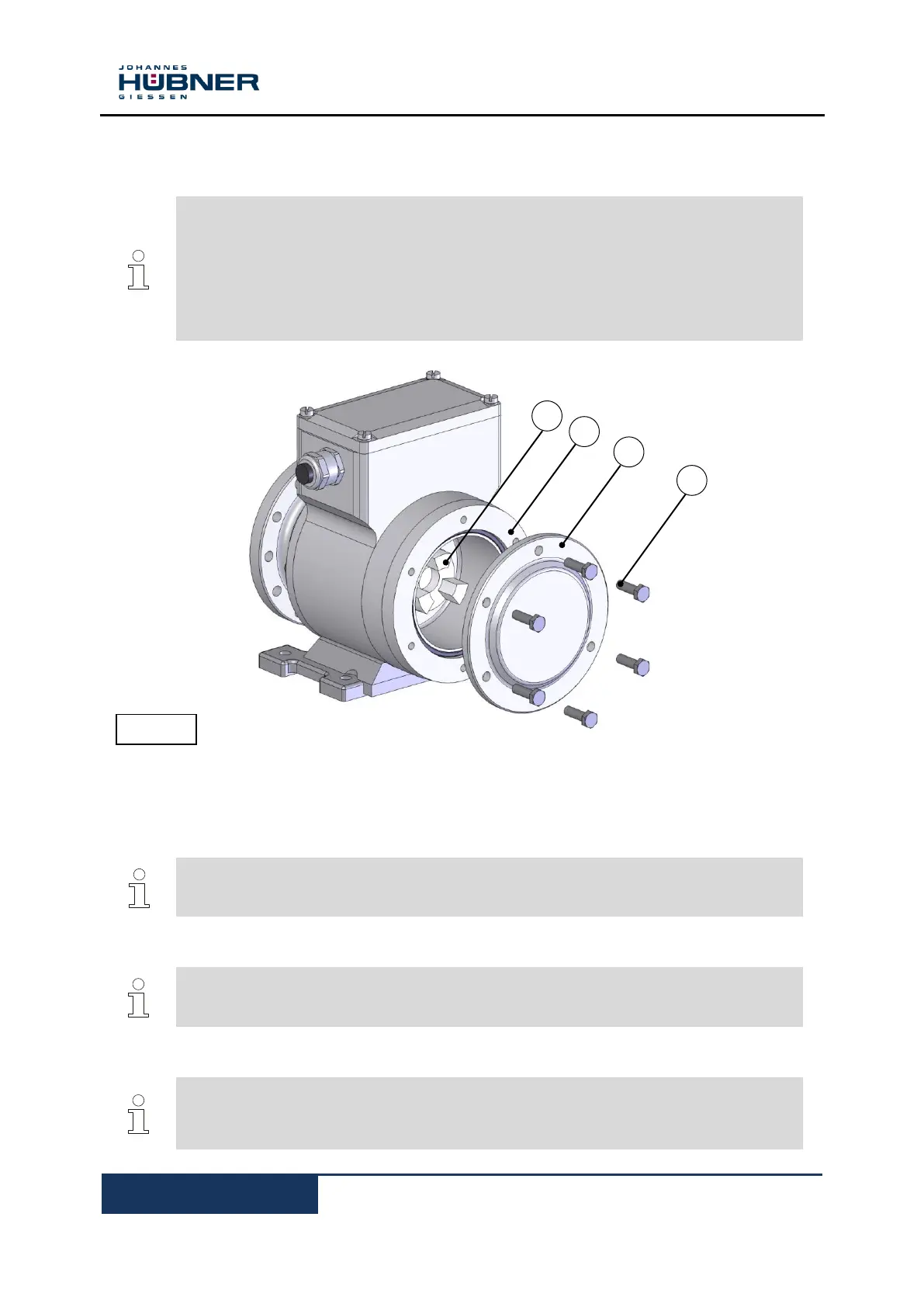
Encoders in construction type B5/B14 have a second shaft end with integrated coupling
half (1) and a B 14 flange (2) on the non-drive end onto which it is possible to fit an
additional device with a B5 flange, for example an incremental encoder, absolute shaft
encoder or an overspeed switch. A second coupling half with elastomer ring (5, Figure
4), which is available as an accessory, is required to fit an additional device.
Installation example see dimension drawing HM 09 M 102 245 (Chapter 11.5).
This design option makes it possible to combine up to four devices.
When supplied ex works the second shaft end is protected by a cover plate (3) secured with 6x M6x20
hexagon head screws (4).
CAUTION!
Do not remove the housing cover secured with Torx screws! These devices are not
equipped with a second shaft end.
1. Loosen the hexagon head screws (4).
NOTES!
The fastening screws (4) can be used later to secure the additional device (7).
2. Remove the cover plate (3).
NOTES!
Ensure no liquids or dirt are allowed ingress into the device when the cover plate is
removed.
Mount the cover again, if you experience installation delays.
 Loading...