24 25
DIMENSIONS
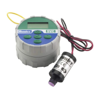
WVC – 3.25" D x 5" H
WVP – 3" W x 11.5" L x 2" H
OPERATING SPECIFICATIONS
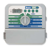
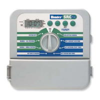
• Station run time: 0 to 240 minutes in 1-minute increments
• Start times: 9 per day
• Day of the week calendar
• Interval watering
• AM/PM or 24-hour clock option
• Start time stacking
• One button manual start and advance
• Programmable rain delay for 1 to 7 days
ELECTRICAL SPECIFICATIONS
• Solenoids: Operates 6 to 9-volt DC latching solenoids
• Hunter DC Solenoid Latching Part: #458200
• Battery: Standard 9-volt alkaline battery (not included), one
year minimum life. Battery not required for program backup.
• Memory: Non-volatile for program data
• Weather sensor compatible
• Frequency of operation: 900 MHz ISM band (U.S./Aust.)
868 MHz (Europe)
PRODUCT
EXPLANATION
This section provides a brief overview of
some of the components of the WVC. Each
item will be discussed in further detail later,
however, this section can be helpful in getting
acquainted with the different options available.
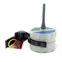
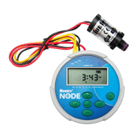
1. WVC Body – The WVC controller is
designed to be dirt tolerant, waterproof, and
submersible to 12 feet.
2. External Antennae – Flexible rubber
antennae for radio communication.
3. 9-Volt Battery Holder – The WVC is
designed to operate on a single 9-volt
alkaline battery. The battery easily snaps
into the battery holder.
4. Wires for DC Latching Solenoids – 24"
leads are provided for wiring DC latching
solenoids. The overlay on the WVC
provides station identication.
5. Weather Sensor Wires – A Hunter
Rain-Clik™ or other Hunter weather sensor
can be connected to the WVC.
6. Valve Mounting Clip – Allows the
WVC to be mounted directly on any
Hunter valve. The clip can also be used in
conjunction with the Universal Mounting
Adapter.
7. Universal Mounting Adapter – Allows for
alternate methods of mounting the WVC.
It can be used to mount the WVC to the
side of the valve box or mounted on a "
(13 mm) diameter section of plastic pipe.
8. LED Indicator – Used when setting WVC
address.
TECHNICAL
INFORMATION
Wireless Valve System
WVC COMPONENTS