Operation Instructions for TCX50H Tire Charger
13
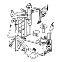
No. Part Number Description
1 RP11-4-123655 DECAL-PEDAL OPERATION
2 RP11-4-402030 DECAL-INFLATRON PEDAL OPERATION
3
128-1484-2 DECAL-HUNTER LOGO TCX50
128-1485-2 DECAL-HUNTER LOGO TCX51
128-1486-2 DECAL-HUNTER LOGO TCX53
4 RP11-4-402021 DECAL-MANUAL TIRE BLEED VALVE
5 RP11-4-115244 DECAL-DANGER OPERATION
6 RP11-4-115243 DECAL-WARNING OPERATION
7 RP11-4-402027 DECAL-MAXIMUM INLET PRESSURE
8 RP11-3020842 DECAL-TABLE ROTATION
9 RP11-4-402023 DECAL-RIM, TABLE, BEAD, BREAKER, BEAD AIR PRESSURE
10 RP11-4-402034 DECAL-MODEL SERIAL NUMBER
11 RP11-4-402031 DECAL-VERTICAL COLUMN LOCK LEVER OPERATION
12 RP11-4-115246 DECAL-ELECTRICAL HAZARD
13 RP11-4-115245 DECAL-WARNING INDICATION
14 RP11-3013640 DECAL-ARROWS LEFT-RIGHT
Electrical Indications
The TCX50H family is manufactured to operate at a specic voltage and amperage rating.
Make sure that the appropriate electrical supply circuit is of the same voltage and amperage
ratings as marked on the TCX50H.
FIRE HAZARD. DO NOT ALTER THE ELECTRICAL PLUG.
WARNING
Plugging the electrical plug into an unsuitable supply circuit will damage the
equipment.
NOTICE
• HAZARDOUS VOLTAGE
• Turn off and lock out system power before
servicing.
• Contact may cause electric shock or death.
DANGER
Make sure that the electrical supply circuit and the appropriate receptacle is installed with
proper grounding.
 Loading...