ISO
HG
con
viscosità
ISO
VG
68
(ad
esempio:
ESSO
Febis
K
68;
Mobil V
actra 2
;
Shell
.
grease
(such
as,
for
example
ESSO
Febis
K68;
Mobil
V
actra
2;
Shell
.
A
TT
E
N
Z
I
O
N
E
:
P
e
r
un
c
o
rr
e
tt
o
f
un
z
i
o
n
a
m
e
n
t
o
n
e
l
t
e
m
p
o
d
e
l
dispositivo
di
sicur
ezza
che
limita
la
pr
essione
alla
pistoletta
di
gonfi
aggio
(vedi
paragrafo
"DISPOSITIVI
DI
SICUREZZA"
a
pag.
8 di
ensabile:
IMPOR
T
ANT!
T
o
ensur
e
corr
ect
operation
of
the
inflation
device
pr
essur
e
limiter
(Refer
to
the
section
on
“Safety
Devices”,
p.
8
of
this
manual,
it
is
essential
to
carry
out
the
following
r
outine
checks:
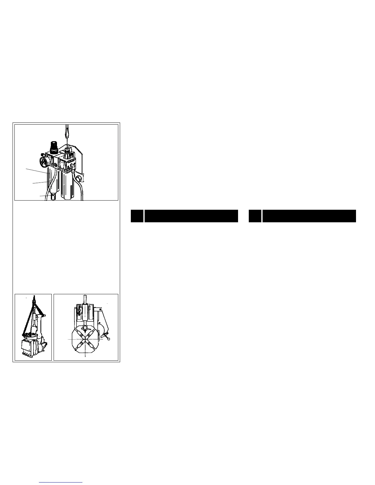
1
2
3
J
1)
V
erificar
e
periodicamente
il
livello
della
condensa
dentr
o
la
tazza
del
filtr
o
(
1,
Fig.
J
)
che
non
deve
MAI
superar
e
la
tacca
(
2,
Fig.
J
)
sul
visor
e
della
tazza.
Quando
necessario
scaricar
e
la
condensa girando, in senso orario, la ghiera (
3, Fig. J
).
2)
Ogni
30
-
40
gior
ni
scollegar
e
la
macchina
dalla
r
ete
pneu
-
matica
e
smontar
e
la
tazza
(
1,
Fig.
J
)
per
rimuover
e
eventuali
impurità solide formatesi all'inter
no di essa.
1)
Check
the
water
level
in
the
water
trap
to
the
air
supply
(
1,
Fig.
J
).
The
level
must
never
go
past
the
notch
(
2,
Fig.
J
)
on
the
a
r
’
s
s
i
g
h
t
g
l
a
ss
.
W
h
e
n
n
e
c
e
ss
a
r
y
,
d
r
a
i
n
t
h
e
w
at
e
r
b
y
t
u
r
n
i
n
g
t
h
e
locking ring (
3, Fig. J
) clockwise.
2)
Every
30-40
days
disconnect
the
machine
fr
om
the
com
-
pr
essed
air
cir
cuit
and
dismantle
the
glass
(
1,
Fig.
J
)
to
r
emove
any solids collected inside it.
13
MOVIMENT
ZIONE
13
MOVING THE MACHINE
Per
ef
fettuar
e
la
movimentazione
della
macchina
pr
ocedere
se
uendo le indicazioni di se
e:
Follow
the
pr
ocedur
es
outlined
below
when
moving
the
ma
-
chine:
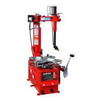
1
) Chiude
e completamente le griffe dell'autocentrante.
2
)
R
u
o
ta
r
e
l
'
a
u
t
o
c
e
n
t
r
a
n
t
e
fi
n
o
ad
a
lli
n
e
a
r
e
i
l
at
i
d
ri
tt
i
d
e
ll
o
s
t
e
ss
o
con la linea ideale dei fianchi della macchina (
vedi fig. H
).
3)
Scollegar
e tutte le fonti di alimentazione della macchina.
4)
Bloccar
e
il
funzionamento
del
pedale
(
7,
Fig.
A)
attraverso
l'apposizione di un cuneo al di sotto dello stesso.
1)
Close
the
tur
ntable
grippers
all
the
way
towar
ds
the
cen
-
tr
e.
2)
T
ur
n
the
table
so
that
the
its
straight
sides
ar
e
lined
up
the
projected line of the side panels (
See Fig. H
).
3)
Disconnect all power sour
ces.
4
e under
neath it.
44
I
H
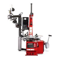
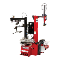
5)
Portar
e
a
fine
corsa
(tutto
indietr
o)
il
braccio
orizzontale
(
11,
Fig. A).
6)
Rimuover
e
il
carter
del
braccio
orizzontale
svitando
le
viti
di fissaggio.
7)
Imbragar
e
la
macchina
con
cinghie
da
carico
di
lar
ghezza
minima 60 mm.
8)
Passar
e
la
prima
cinghia
dietr
o
il
braccio
orizzontale
come
mostrato in
Fig. I.
9
)
P
a
ss
a
r
e
l
a
s
e
c
o
n
da
c
i
n
g
h
i
a
f
r
a
i
d
u
e
s
c
a
ss
i
a
n
t
e
ri
o
ri
d
e
l
p
i
att
o
autocentrante come mostrato in
Fig. I.
5)
Move the horizontal arm (
11, Fig. A)
all the way back.
6)
Remove
the
horizontal
ar
m
casing
by
r
emoving
the
fixing
scr
ews.
7)
Sling the machine with lifting straps at least 60 mm wide.
8
)
Pa
ss
the
firs
t
s
t
ra
p
b
e
hi
n
d
t
he
hori
zont
a
l
a
r
m
a
s
s
how
n
i
n
Fig. I.
9)
Pass
the
second
strap
between
the
two
fr
ont
slots
on
the
tur
ntable plate as shown in
Fig. I.
10)
Pass
the
straps
thr
ough
a
lifting
hook
above
the
machine
as shown in
Fig. I.