SERVICE WORK ON THE CHASSIS 12
59
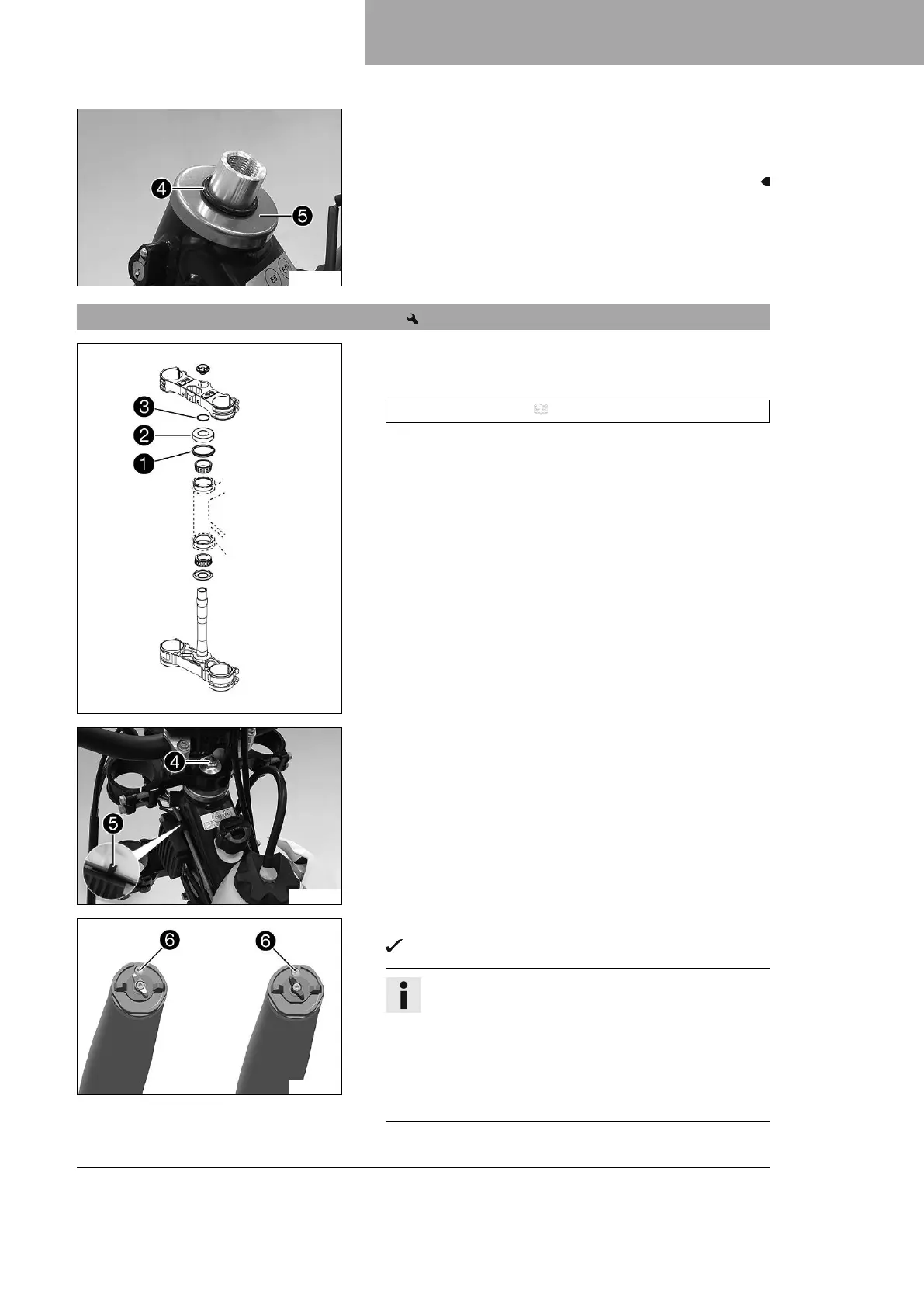
H03683-10
–
Remove O-ring
4
. Remove protective ring
5
.
– Remove the lower triple clamp with the steering stem.
– Remove the upper steering head bearing.
12.10 Installing the lower triple clamp
B01632-10
Main work
– Clean the bearing and sealing elements, check for damage,
and grease.
High viscosity grease ( p. 157)
– Insert the lower triple clamp with the steering stem. Mount
upper steering head bearing.
–
Check whether upper steering head seal
1
is correctly posi-
tioned.
–
Mount protective ring
2
and O-ring
3
.
H03684-10
– Position the upper triple clamp and handlebar.
–
Mount screw
4
, but do not tighten it yet.
–
Mount the clutch line with cable holder
5
.
S04824-14
– Position the fork legs.
Bleeder screws
6
are positioned toward the front.
Info
The compression damping is located in left fork
leg COMP (white adjuster). The rebound damping is
located in right fork leg REB (red adjuster).
Grooves are milled into the side of the upper end of
the fork legs. The second milled groove (from the top)
must be flush with the upper edge of the upper triple
clamp.
 Loading...

