28
1. FOGGER SYSTEM MOUNTING
a. Physical location
i. Remove t he rear skirt fo r easy access t o the tray, GFCIs and case thru hole(s).
ii. When ready, connect the fogger power to the GFCI labeled “Fogging System”.
This circuit is switched at the case control panel as opposed to the adjacent GFCI
which is hot once the case power connections are made.
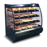
Figure 2: Rear of case showing panel cutout and access
panel.
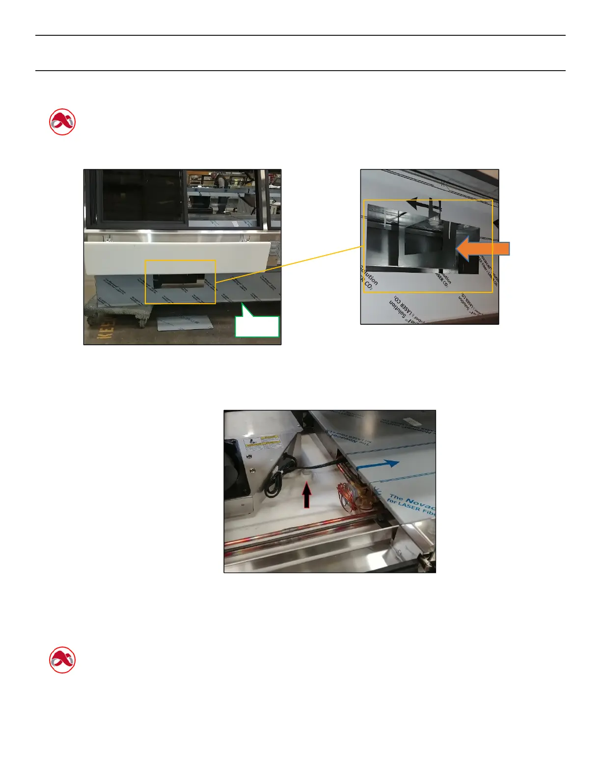
Figure 3: The provided tray directly behind the
access panel. Remove lower skirt for system
installation. The access panel is provided for ease
of system access during operation.
Figure 4: Provided case drop to route hoses and nozzle heater wiring.
2. FOGGER NOZZLE INSTALLATION
a. Heated nozzles must be utilized. Standard (no n-heated) nozzles will freeze and render the
system inoperable. The bracketry design will no t accommodate non-heated nozzles.
b. Gain access to the coil area by removing the deck pans. The coils, fans and refrigeration
piping will be exposed. Locate the nozzle mounting bracketry