30
3. WATER AND AIR HOSE ROUTING
a. Trim the black hard plastic tubing (see figure 6, pg 3) surrounding the 3 lines coming out
of each heated nozzle, ahead of the case drop (figure 4, pg 2). Do not pass the hard
plastic through the case drop.
b. Pass the nozzle tubes and wiri ng through the case drop and ensure no excess tubing
remains in the case. Leave enough slack so that the tubes do not kink when passing
through the drop and nozzle service can be accomplished.
c. IMPORTANT! - Ensure that the w ater lines DO NOT COME IN CONTACT with the below
freezing temperature of the refrigeration suction lines.
d. M ake the appropriate water and air connections to the fogger system under the case.
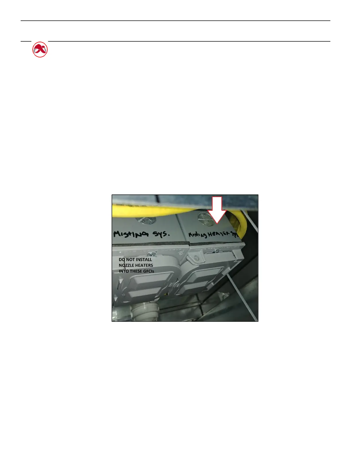
e. Make the appropriate electrical connectio ns for the nozzle heaters. Plug the heaters
into the provided GFCI when the fo gger system is ready to run. Do not plug it into the
“fogging system” GFCI. Note: The heater GFCI is electrically hot once the case electrical
connections are made, therefore the nozzles will be heate d once the heater is plugged in.
f. IMPORTANT! - Seal case drop with a silicone based sealant o nce installation is finalized.
Allow the recommended t ime to cure before first operation of the fogging system.
Figure 8: Do not plug the heater into the Fogging System GFCI and vice versa.