APPENDIX 6
Ref: MINIFLEX LR MANUAL Rev. 0 64
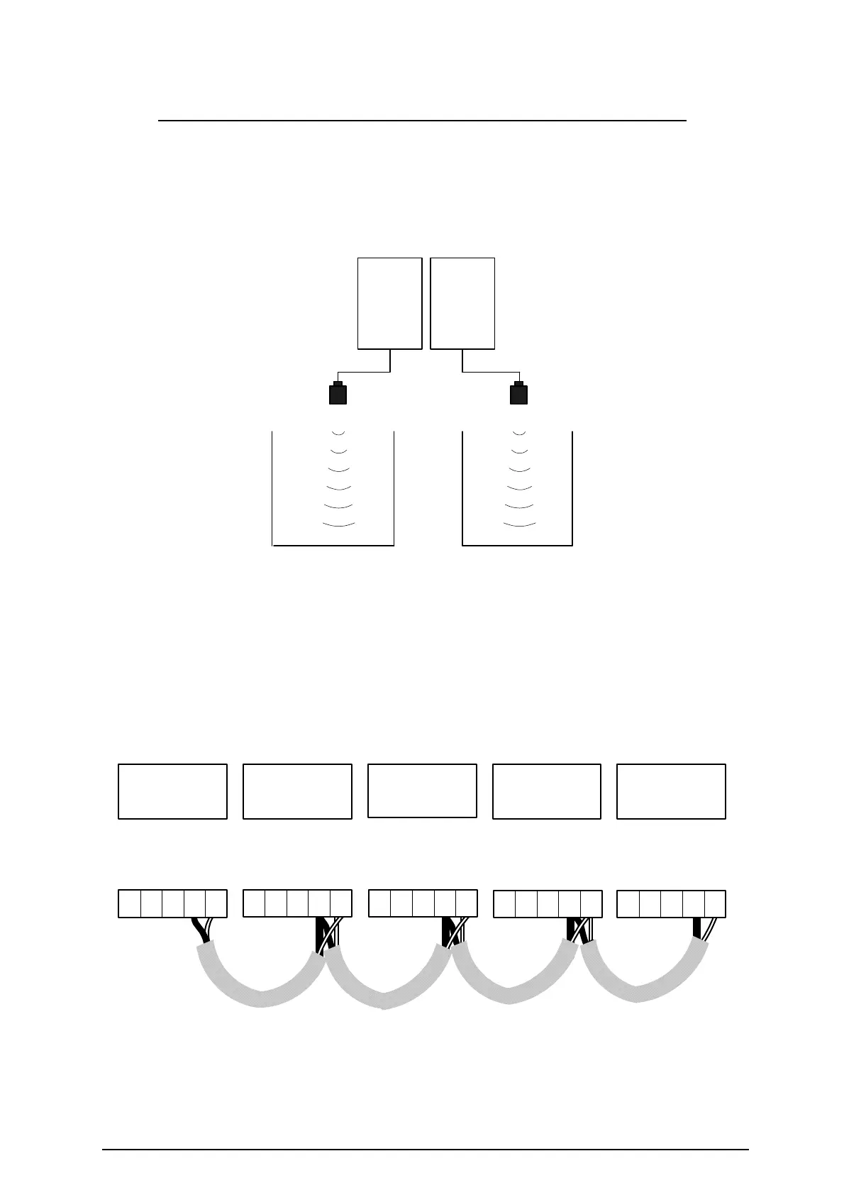
WIRING DIAGRAM FOR SYNCHRONISATION OF INSTRUMENTS
If two or more instruments are situated close together or the transducers beam profile
overlaps there is a possibility they can interfere with each other.
Potential problem application with two instruments located close together.
To solve this problem, connect the sync and shield terminals of each of the units in close
proximity to each other as shown below.
To program one instrument as master give it the ID number 1 (Pr 12.6 = 1) then set each of
the attached instruments as slaves (Pr. 12.7 = Slave) with consecutive ID numbers, up to a
maximum of 5.
Connection diagram for up to 5 instruments
SYNC
SYNC
SYNC
SYNC
SYNC
SHIELD
SHIELD
SHIELD
SHIELD
SHIELD
9
10
876
9
10
876 9
10
876
9
10
8769
10
876
Instrument 1
Pr. 12.6 = 1
Pr. 12.7 = Master
Instrument 2
Pr. 12.6 = 2
Pr. 12.7 = Slave
Instrument 3
Pr. 12.6 = 3
Pr. 12.7 = Slave
Instrument 4
Pr. 12.6 = 4
Pr. 12.7 = Slave
Instrument 5
Pr. 12.6 = 5
Pr. 12.7 = Slave
MASTER
SLAVE
Instruments located
in close proximity
 Loading...