SECTION 1
Transducer Mounting
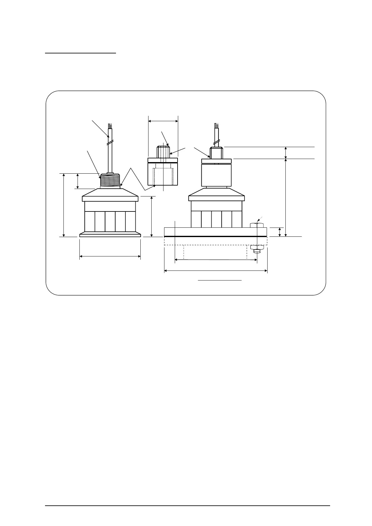
The transducer can be supplied as 'standard' or mounted in a flange. For applications
requiring chemical compatibility the transducer is available fully enclosed in PVDF in a
standard mounting or with flange. Figure 4 shows the dimensions:
Figure 4: Transducer mounting diagram
An isolation kit is provided with each transducer to minimise any ringing transmitted through
the mounting structure.
The transducer must be mounted perpendicular to the monitored surface and, ideally, at least
0.5 metres above it.
The transducer has a 12° inclusive conical beam angle at -3dB and must be mounted with a
clear unobstructed sight of the liquid to be measured over the complete measurement range.
The transducer is provided with integral cable which can be extended up to 300 metres using
a suitable junction box and RG62AU cable. The temperature compensated transducer
requires an additional single core screen extension, or twin-ax cable.
Refer to Page 8 for full details.
Transducer cables and temperature compensation cables can be run together but
should be separated from power cables by at least 150mm and preferably installed in
their own earthed steel conduit.
Isolation Kit
Fit as shown
102
M20 x 1.5
50 dia
M32 x 1.5
62
26
92 dia
10m cable 6.0 dia
20
130
assembled
height
20
Dia to suit flange selected
No. & size of bolts
to suit flange selected
Bolt hole PCD to suit
flange selected
INTEGRAL FLANGE
Ref: MINIFLEX LR MANUAL Rev. 0 5