SECTION 1
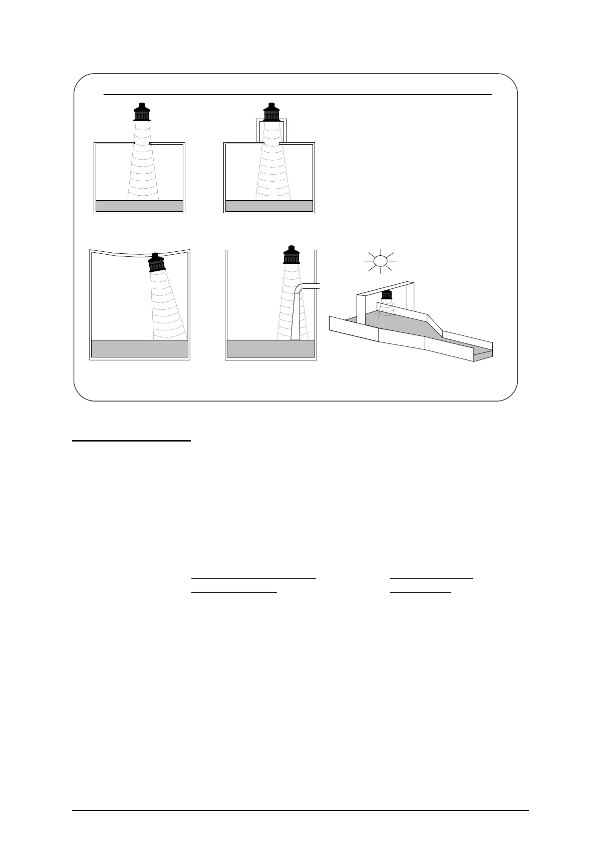
KEEP TRANSDUCER
PERPENDICULAR
TO LIQUID.
KEEP TRANSDUCERS AND
TEMPERATURE COMPENSATION
PROBES OUT OF DIRECT
SUNLIGHT
DO NOT AIM THROUGH
HOLES IN THE TANK
AVOID ROUGH EDGES
IN STANDPIPES
AVOID INFLOWS OR
OTHER OBSTRUCTIONS
CAUTION: AVOID THE FOLLOWING TRANSDUCER INSTALLATION FAULTS
Figure 6: Transducer installation faults
Standpipe Installations
In many applications access to a vessel must be made via a standpipe. However, it is
necessary to observe some basic rules when fitting transducers into standpipes.
BLANKING: Parameter 4.0 should always be set at least 150mm longer than the
length of the standpipe.
STANDPIPE should be in accordance with the following table
DIMENSIONS:
Flange size and minimum
Maximum length
bore of Standpipe
of Standpipe
3" ( 80mm) 300mm
4" (100mm) 300mm
e.g. Using a 4" flanged transducer would require the standpipe length to be no more than
300mm and Pr.4.0 set at 450mm minimum.
The inside of the pipe and joint with vessel top must be clean and free of any
obstructions, seams or welds.
Ref: MINIFLEX LR MANUAL Rev. 0 7