10
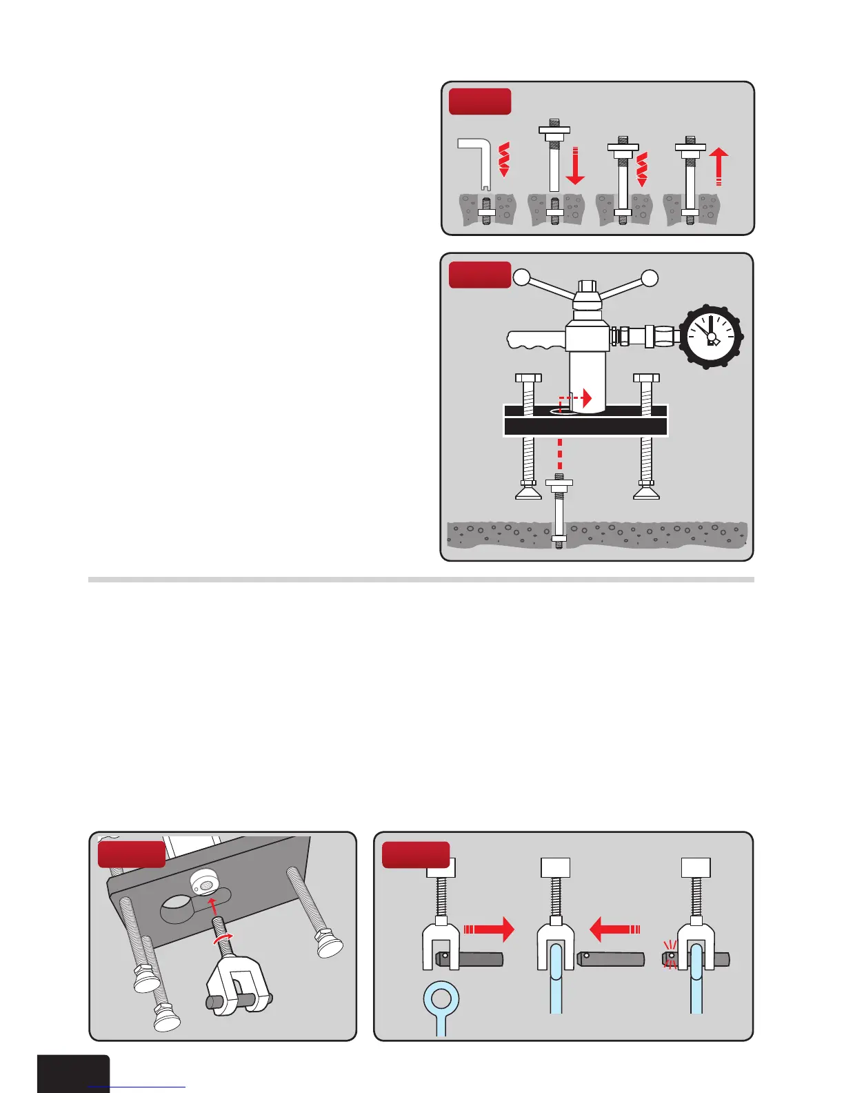
For testing ringbolts the Clevis adaptor is used.
Mount the locking adaptor into the tester (see Section 1 General testing procedure). Then
thread the clevis adaptor into the tester body until it is fully engaged, using a quarter turn
for positioning (g 18).
Remove crosspin from the clevis adaptor and offer the tester and bridge to engage eye of
the anchor in the clevis. Some adjustment will be required on the swivel feet, so that this
tisachieved.Pushclevispinthroughtheclevisandeyebolt,ensuringthattheballonthe
pin clicks into place, having passed through the second fork (g 19).Oncettedsecurely
commence testing (see Section 1 General testing procedure).
Fig 19
Fig 18
2.5 THE CLEVIS ADAPTOR
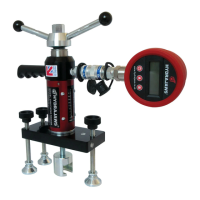
2.4 M5, M6, M8 AND M10 THREADED ROD ADAPTORS
Fig 16
The M5 and M6 threaded rod adaptors are
equipped with an external M12 thread for
use in conjunction with the M12 threaded
button adaptor. They are used primarily
for testing remedial wall ties. The M8 and
M10 threaded rod adaptors are equipped
with an M16 external thread and the M16
nutttedwithconnectstothepullingslot
in the tester or bolt tester adaptor.
Connect the threaded rod adaptor
complete with the M12 button adaptor to
thethreadonthexing(g 16).
Removethelockingadaptoriftted(see
Section 1 General testing procedure).
Adjust the length of the bridge legs and
the height of the button adaptor/nut so that
the adaptor can pass through the hole in
the bridge and engage it in the pulling jaw
of the tester (g 17).
Level the load spreading bridge with the
adjustable legs before commencing the
application of the load.
Fig 17