14
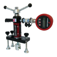
4. SAFETY HARNESS EYEBOLT TESTER KIT
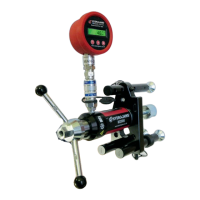
TESTING A SAFETY HARNESS EYEBOLT
(g 22)
TESTING A LADDER RESTRAINT HOOK (g 23)
For testing Safety Harness Eyebolts to the
requirements of BS5845 and BS EN795
Protection Against Falling From A Height,
Anchor Devices - Requirement for Testing
and BS 7883: 2005 BS 788: 2005 code of
practiceforDesign,Selection,Installation,
Use and Maintenance of Anchor Devices
conforming to BS En 795. The kit may
also be used for testing Ladder Restraint
Hooks and most Ringbolts in concrete or
masonry.
The Tester is factory assembled with the
ringbolt adaptor screwed into the M12
locking adaptor located in the Tester jaw
and the 150 load spreading bridge with the
three 75mm hexagon legs with swivel feet
with25mmofneadjustment.
KIT CONTENTS:
• 2000 model Medium Duty Tester with
xedGaugeto15kN*
• 150mm Load Spreading Bridge
• 75mm Hex Extension Legs (3)
• M12 Ringbolt Adaptor with
Locking Adaptor
• Turning handle with integrated
operating 22mm nut
•CalibrationCerticate
• Padded Carrying Case
* Some models have removable gauge and
coupler system
Placethebridgeovertheeyebolttobetested.Locatetheclevisontheeyeboltandtthe
cross pin through the clevis and eyebolt, ensuring that the ball on the pin clicks into place,
having passed through the second fork (see section 2.5 The Clevis Adaptor).
Adjust the swivel feet by unscrewing from the hexagon leg, so that each foot is resting on
the material around the eyebolt and the bridge is square and level. Fit a protection plate
betweenwallandbridgefeetifnecessary,toprotectsoftdecorativenishes.
Check that the black gauge pointer is resting on zero and set the red maximum indicator
pointer to zero, by turning the knob on the gauge window anticlockwise.
Commence the test by turning the operating handle on the tester clockwise and observe
the gauge as the load on the eyebolt is increasing. Continue applying the load until the
proof test load of 6kN is reached with the black gauge pointer. Stop applying the load and
observe if the black pointer falls back, leaving only the red pointer at the maximum load
achieved.
Ifthefallbackisminimal,applytheloadagainuntilbothpointersareattheprooftestload
and the structural anchorage should then sustain the force for a minimum of 15 seconds.
Follow the same setting up procedure as for Safety Harness Eyebolt test, and apply the
load gradually until the required proof load of 2.5kN is reached or failure occurs. Observe
if the hook withdraws from the structure or the test load cannot be achieved. This would be
considered a failure and must be taken out of service