11
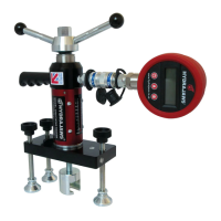
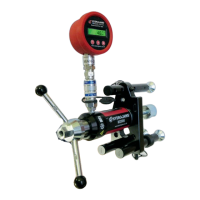
3. SCAFFOLD TESTER KIT
The Hydrajaws Test meter is part of a
purposemadesystemfortestingxings
and measures the load supplied. The
Scaffold Tester Kit has accessories
designed to test Scaffold Anchors and
Ringbolts to the requirements of the
guidance note TG4-04 issued by National
Access and Scaffolding Confederation
(NASC) and the Construction Fixings
Association (CFA).
The Tester is factory assembled with the
bolt tester adaptor screwed into the M12
locking adaptor located in the Tester jaw,
and the three 100mm hexagon legs with
swivelfeetxedtothe150loadspreading
bridge. Further adjustment available in the
foot (20mm).
KIT CONTENTS:
• 2000 model Medium Duty Tester
withxedGaugeto20kN*
• 150mm Load Spreading Bridge
• 100mm Hex Extension legs (3)
• Turning handle with integrated
22mm operating nut
• M16 Hex Setscrew
• Bolt Tester Adaptor
• M12 Ringbolt Adaptor Clevis
• M12 Locking Adaptor
•CalibrationCerticate
• Padded Carrying Case
* Some models have removable gauge and
coupler system
TESTING OF M16 DROP IN SCAFFOLD TIE ANCHORS
Fit the M16 hexagon setscrew to the anchor, ensuring at least two complete turns for
ample thread engagement. Offer Tester with bridge to the hexagon head of the setscrew
and engage head in bolt tester adaptor jaw. Make adjustment on each swivel foot by
unscrewing from the hexagon extension legs so that each foot is resting on the material
around the anchor and the bridge is square and level.
Check that the black gauge pointer is resting on zero and set the red maximum indicator
pointer to zero by turning the knob on the gauge glass anti-clockwise.
Commence the test by turning the operating handle on the Tester clockwise and observe
the gauge as the load on the anchor is increasing. Continue applying the load until the
proof test load is reach (kN) with the black gauge pointer. Stop applying the load and
observe if the black pointer falls back, leaving the red pointer at the maximum load
achieved.Ifthefallbackontheblackpointerisminimal,applytheloadagainuntilboth
pointers are at the test load required and leave the test load in place for approximately
10 seconds.
Should the black pointer not reach the maximum test load requirement, or the
operating handle has to be turned to maintain the load, it is certain that the anchor will
have failed the test.