9
Remove the insulation around the fastener.
Mount the locking adaptor into the tester (see
Section 1 General testing procedure). Thread
the insulation adaptor into the locking adaptor
fully then back off until horizontal.
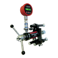
By holding the tester, slide the head of the
insulation fastener (a) between the two plates
withthestemofthexingrestingintheslotin
the lower plate (b) and adjust the legs on the
load spreading bridge to suit the base material.
Ensure that the pull-out force acts along the
axisofthexingbeingtested(g 15).
Hexagonal leg extensions may be required to
reach an insulation fastener that is raised.
2.3 THE INSULATION ADAPTOR
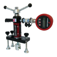
2.2 M10, M12, M16 AND M20 THREADED STUD ADAPTORS
Fig 12
Suitable for testing sleeve and stud anchors.
(g 12) After the anchor has been set
in accordance with the manufacturers
recommendations, a suitable threaded
rod (a) is screwed into the anchor and the
adaptor (b)thentted.Thelengthofthe
threaded rod to be screwed into the anchor
must be at least equal to the diameter of the
anchor.
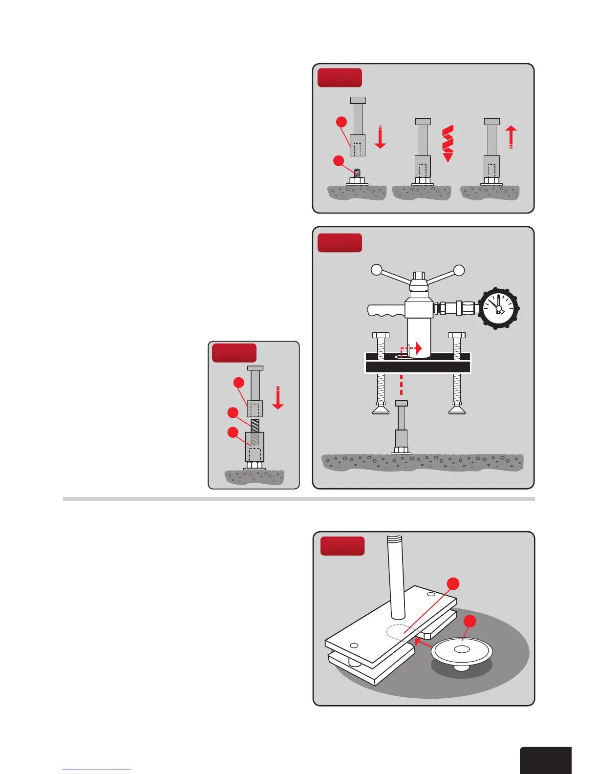
Removethelockingadaptoriftted(see
Section 1 General testing procedure).When
theadaptorissecurelyttedtotheanchor
thread position, place the tester over the
adaptor, passing the head through the hole
in the bridge and engage it in the pulling
jaw of the tester (g 13). Level the load
spreading bridge with the adjustable legs
before commencing the application of
the load.
Fig 13
b
a
1 2 3
Fig 15
b
a
Note: (g 14) To use
the optional M30 HD
Threaded stud adaptor,
rstattach45mmM20
thread piece (c) into
adaptor (e) and attach to
thexing.Thenthread
the M20 Adaptor (d)
and proceed as above.
Hexagonal leg extensions
may be required.
d
c
e
Fig 14