5
1. GENERAL TESTING PROCEDURE
SETTING UP THE TESTER
1 Fit the appropriate adaptor to the tester.
Example shown is a bolt tester adaptor.
(Forttingofotheradaptorspleasesee
individual instructions in this manual).
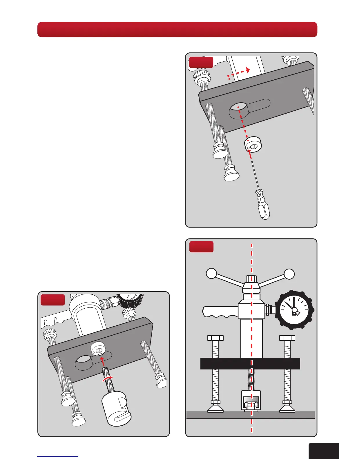
2. The tester is supplied with a locking
adaptorttedintothetesterbody.
This locking adaptor can be removed
forttingofdifferentadaptorsbyusing
the 3mm Ball Driver. When replacing
back in ensure it is fully engaged into
the tester body before tightening
(g 1). Thread the bolt tester adaptor
into this, until it is fully engaged, using
a quarter turn for position (g 2).
3.Makenaladjustmentssothatthebolt
testeradaptor,testerandxingare
aligned (g 3).
4. Position the tester so that the gauge
can be easily read.
5. Adjust the length of the threaded legs
so that all three are in contact with the
base material and the load spreading
bridge is aligned and level by referring
to the bubble levels on each face.
Fig 3
Fig 2
Fig 1