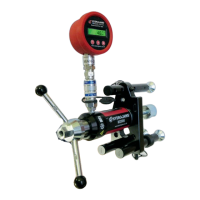
Fig 29
Interfacialfailure
to dolly.
Cohesive failure of
the adhesive.
Interfacialfailure
to substrate.
Substrate failure.
6. Apply adhesive to substrate test surface (g 26a). This ensures the adhesive wets out
both surfaces and helps prevent interfacial failures.
7. Pressthesteeldollyintothesubstratetestsurfacewitharmpressure(g 26b)
DONOT‘seat’thedollybytwistingitintoposition.Ifthedollyistwistedintopositionit
will increase the likelihood of interfacial failures.
8. Remove excess adhesive from around the edge of the dolly without disturbing its
position (g 26c). This ensures a consistent bond area and will therefore help reduce
variationsinthetestresults.Ifworkingonaverticaloroverheadsurface,ensurethe
dolliesareheldrmlyinpositionuntiltheadhesivehascured.
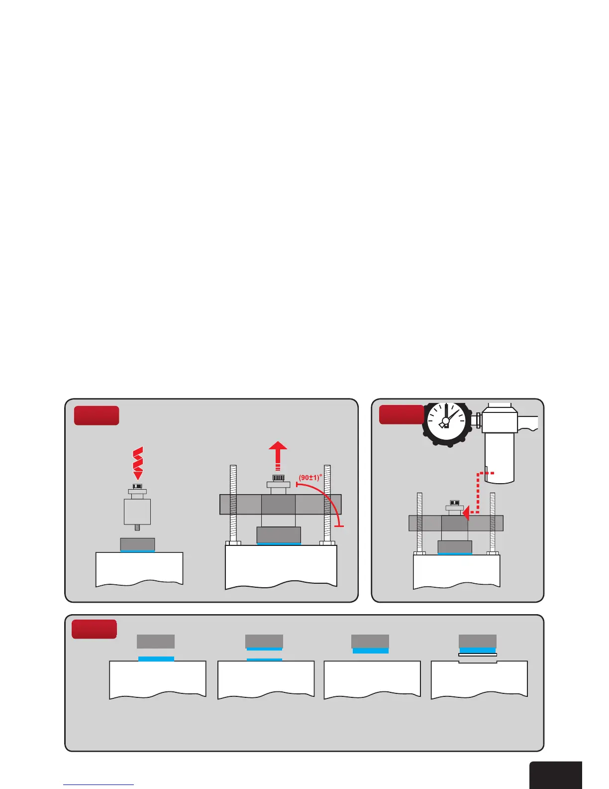
9. Connect centering plug to disc using the 8mm thread and hand tighten until bottom is
ushwithtopdisc(g 27a).
10. Lower load stool centre hole over centering plug and adjust the 3 screws until top of
plugisushandlevelwithtopofstool.Itisessentialthatthislevellingiscarriedout
carefully to ensure a square and smooth pull through the stool. The load applied to the
centre of the dolly should be at an angle of 90º±1 (g 27b).
11.SlideTesteroveradaptorontopofplugandt22mmsocketandratchettothe
operating nut (g 28). Secure equipment so that it does not move during testing.
This will cause excess misalignment which will reduce pull-off strengths.
12. Operate ratchet in a clockwise direction until required loading is obtained or bonding
breaks. Record test temperature, failure load and failure mode (g 29) (Record mixed
failure modes in percentages of bond area, i.e. 90% substrate failure, 10% cohesive
failure). Maximum loading achieved will be shown by red indicator pointer. Use this
reading to calculate the bond strength Mpa from the chart on page 20.
a
b
TEST SURFACE