12
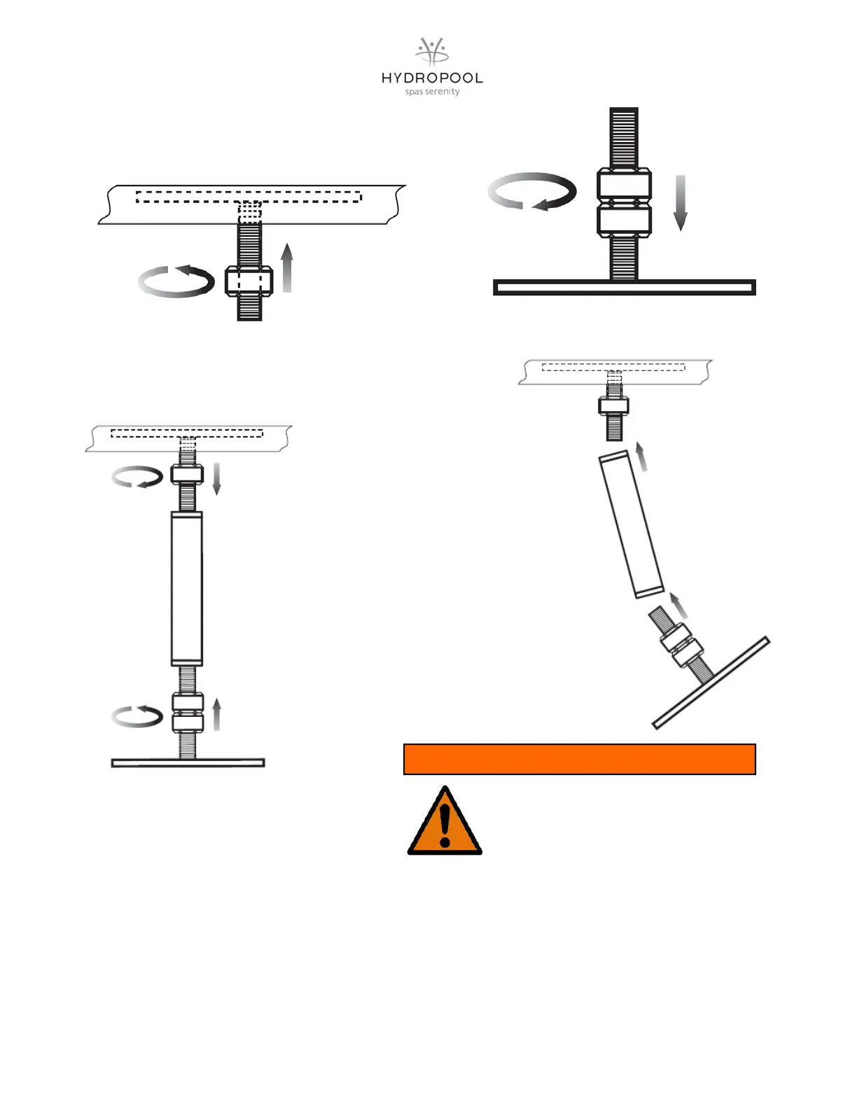
1 Thread one hex nut all the way up to the top of the
threaded posts attached under the lip.
2 Thread two hex nuts down to within 2.5 cm (1 in.) of bot-
tom of foot plate
3 Slide the foot plate assembly onto one end of the square support leg,
then slide the leg onto the threaded post under the swim spa lip.
4 Bring the two hex
nuts on the foot plate
up about 5.1 cm (2
in.) and the hex nut
on the threaded post
under the swim spa
lip, down about 5.1
cm (2 in.). Finger
tighten until the leg is
secure. Loosen the
hex nuts on the hori-
zontal rod so that the
leg is level and
tighten until the leg is
secure.
5 After the swim spa is filled with water, the legs can now be adjusted as necessary from either the top or bottom with
a wrench to ensure that the walls are straight and level.
While the swim spa is filling, it may be necessary to adjust the steel support legs while filling with water. Should the
unit bow outward, lengthen the steel support leg by turning the top nut counter clockwise on the bottom foot. Should
the shell bow inward, shorten the steel support leg by turning the top nut clockwise.
Be careful to only adjust the nut 1/4 or 1/2 a turn at any one time. Do not extend the leg length too much as this may
cause deformation on the top flange. Adjustments may be necessary on more than one leg.
DO NOT OVER-EXTEND THE STEEL SUPPORT
LEGS AND/OR SUSPEND SHELL ABOVE THE
FLOOR AS THIS WILL CAUSE STRUCTURAL
DAMAGE AND VOID WARRANTY
WARNING