13
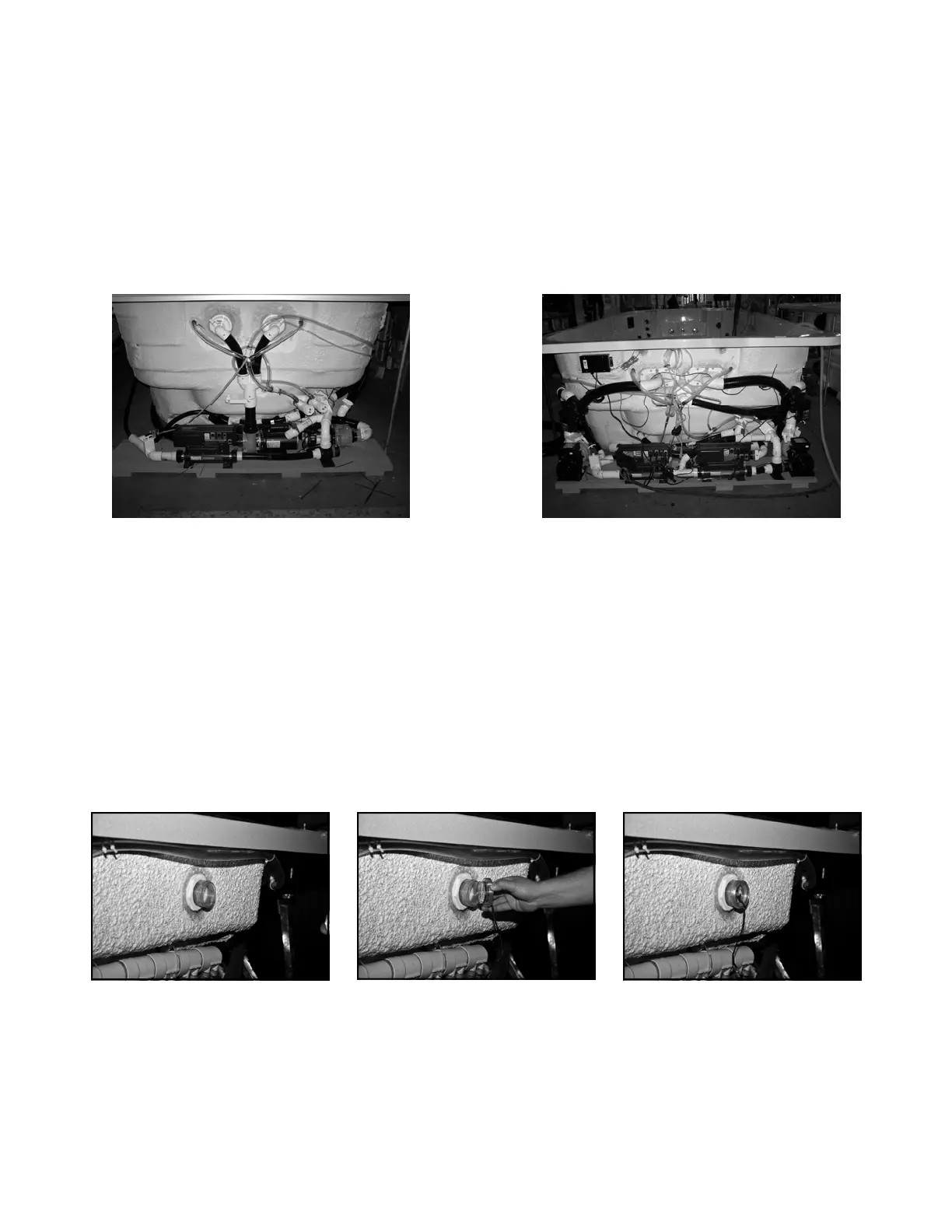
SUPPORT EQUIPMENT ASSEMBLY (NON CABINET MODELS ONLY)
Position equipment platform next to the swim spa under the swim jets. Do not remove support equipment from platform.
All necessary o-rings are bundled and shipped in the accessories bag. Carefully install o-rings into unions and hand
tighten all connections. Ensure that o-rings are properly seated and do not get pinched while connecting the unions as
this will result in leaks. Union connections are located on the swim spa control heater manifold, pipe to pipe connec-
tions and all pumps.
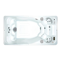
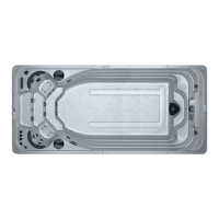
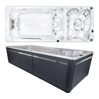
AQUATRAINER SUPPORT
EQUIPMENT PLATFORM
OPTIONAL OZONATOR CONNECTION
The clear 9.5 mm (3/8 in) ID ozonator tube is
shipped coiled and attached to the back of the
swim jets. Attach loose end to barb on ozonator,
and ensure that the ozone check valve is oriented
vertically.
NOTE: EQUIPMENT MAY NOT BE EXACTLY AS SHOWN
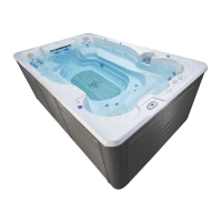
AQUASPORT SUPPORT
EQUIPMENT PLATFORM
LED LIGHT ASSEMBLY
The light wire harnesses are bundled & attached to the control box on the equipment platform. One light is located on the
riser of the middle step and the other is part of the self clean system located under the swim jets.
TOPSIDE CONTROL PANEL CONNECTION
Connect the topside control panel cable (located on equip-
ment platform) to the master spa pack on the left hand
side. If you connect to the slave heater pack, you will get
an “SLA” error message and not all functions will work
properly.