1.0 Operator Controls
CC1092267A 5
1 Operator controls / arrangeme nt
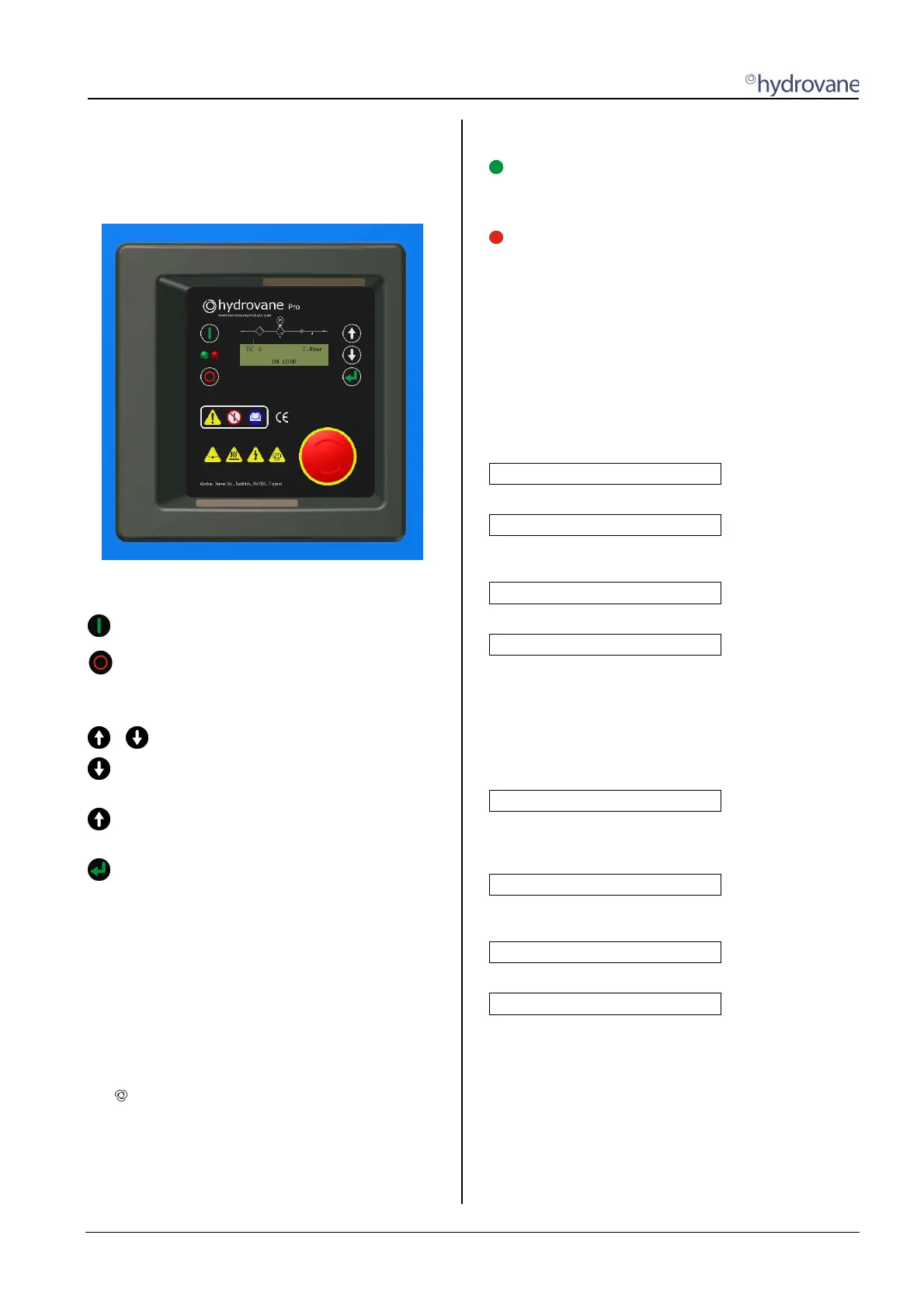
1.1 Keys
When power is applied the controller display illuminates
to show compressor output values and status
messages.
The two keys on the left above and below the green
and red LED’s have a single function:
Start key.
Stop key.
The three keys on the right next to the display have a
dual function:
+
Call up or exit menu / sub-menu.
Switch to next sub-menu / menu item, or
reduce a value.
Switch to previous sub-menu / menu item, or
increase a value.
Reset/Enter key.
In a menu / sub-menu, the reset key functions as
an enter key.
1.2 Status indicator (display / light
signals)
The controller is fitted with a three-row display.
The first row permanently displays compressor
discharge temperature and system pressure.
The following symbols may also be used in the 1st row:
p
2
Second pressure range
Remote start / stop activated
The second row is reserved for menu items, values like
the total service hours and set values like nominal
pressure are viewed here.
The third row shows status, fault and warning
messages.
The HYDROVANE Pro is fitted with two light signals (red,
green).
Flashing, system is ready, the motor may start up
automatically at any time.
Lit up permanently, the drive motor is running
Flashing slowly, warning, maintenance due
Flashing rapidly, fault, unit is stopped until fault has
been rectified
The red light signal only goes out once the warning or fault
has been rectified and confirmed using the Reset/Enter
key.
1.2.1 Speed indicator in the display
The speed is displayed in the 2nd row of the display. If the
menu navigation is displayed, the speed display is faded
out.
Examples of speed displayed:
[ _________❚___ ] 3290rpm
Speed in controlled range.
[ ❚____________ ] 1300rpm
Speed in lower controlled range,
minimum speed not yet reached.
[ |___________ ] 1280rpm
Minimum speed reached.
[ ___________| ] 3650rpm
Maximum speed reached.
1.2.2 Status messages in display
The status messages are shown in the 3rd row of the
display. With longer texts, the indication may 'alternate'.
Status messages:
INITIALIZATION VSD...
The compressor's supply voltage has been switched on.
The control system is being initialised and is setting up
communication to the inverter (VSD).
READY TO START
The unit is ready to start and can be switched on (see
Section 2.1).
WARNING START WITH ...
alternating with
... PRESSURE REQUIREMENT
The unit has been switched on and is ready. The unit starts
automatically following the pressure requirement from your
system.