Home
Hynautic
Control Unit
04 Series
Hynautic 04 Series User Manual
4
of 1
of 1 rating
36 pages
Give review
Manual
Specs
To Next Page
To Next Page
To Previous Page
To Previous Page
Loading...
Page 15 of 36 Pages
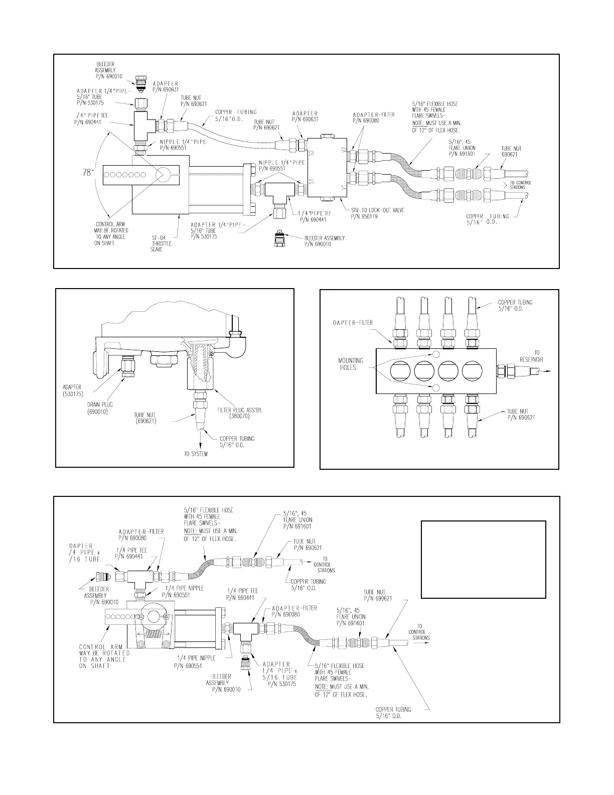
Figure 17. ST-04 Throttle Slave with STV-10 Lock-Out Valve
Figure 18. Ports on Bottom of R-04 Reservoir
Figure 19. MCV-04 Charging Valve
Figure 20. SS-04 Shifter Slave
NOTE
The Tube Fitting and Bleeder
Valve may be reversed on
the Pipe Tee to allow for
easier tube connec
tion.
14
16
Table of Contents
Table of Contents
3
Teleflex Morse Engine Control System
4
Why It Works
4
Preparation for Installation
4
Component Installation
4
Sender Installation
4
Throttle Slave Installation
6
Clutch Slave Installation
8
Tubing Installation and Connection
10
Rules for Routing Tubing
10
Install Tubing between Senders and Slaves
11
Filling and Bleeding System
11
Filling the System
11
Bleeding the System at Slave
11
Bleeding the System at Senders
12
System Fluid
12
Making the System Operational
12
Synchronizing the Controls
12
Connecting Engine Controls
12
Operation
12
Throttle Senders
12
Clutch Senders
13
Maintenance
13
System Parts List (Nylon)
16
System Parts List (Copper)
17
Templates
25
Cdf-04 Mounting Plate
27
Plan I-Twin Engine, One Station
28
Plan II-Twin Engine, Two Station
29
Plan III-Twin Engine, Three Station
30
Plan IV-Twin Engine, Four Station
31
Circuits
31
Plan III-S
33
Plan IV-S
33
Troubleshooting
34
4
Based on 1 rating
Ask a question
Give review
Questions and Answers:
Need help?
Do you have a question about the Hynautic 04 Series and is the answer not in the manual?
Ask a question
Hynautic 04 Series Specifications
General
Brand
Hynautic
Model
04 Series
Category
Control Unit
Language
English