OPERATION
4-2 powermax30 Operator Manual
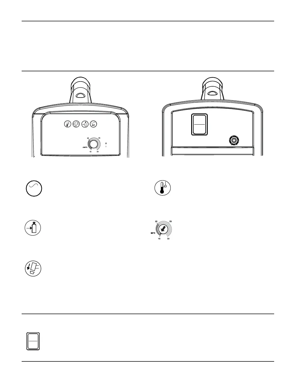
Controls and indicators
The Powermax30 has an ON/OFF rocker switch, an amperage adjustment knob and 4 indicator
lights, which are described below.
I
O
120V
15
A
120V
20
A
240V
2
0
A
I
O
Rear controls
ON (I)/OFF (O) power switch
Activates the power supply and its control circuits.
Gas pressure LED (yellow)
When illuminated, this LED indicates
that the gas pressure is below 40 psi
(2.8 bar). Correct this condition before
you continue.
Torch cap LED (yellow)
When illuminated, this LED indicates
that the consumables are loose,
improperly installed, or missing.
Power ON LED (green)
When illuminated, this LED indicates
that the power switch has been set at I
(ON) and that the safety interlocks are
satisfied.
AC
Front controls and LEDs
Temperature LED (yellow)
When illuminated, this LED indicates
that the power supply temperature is
outside the acceptable operating
range.
Amps adjustment knob
Use this knob to set the output
current between 15 and 30 amps.
Front
Rear
Some fault conditions will cause one or more of the LEDs to blink. For information on what these
fault conditions are and how to correct them, see Basic troubleshooting in Section 5.
PMX30_OM_04.qxp:PMX30_OM_04 10/7/09 12:45 PM Page 4-2