Reference Surface
Reference Surface
Reference Surface
Reference Surface
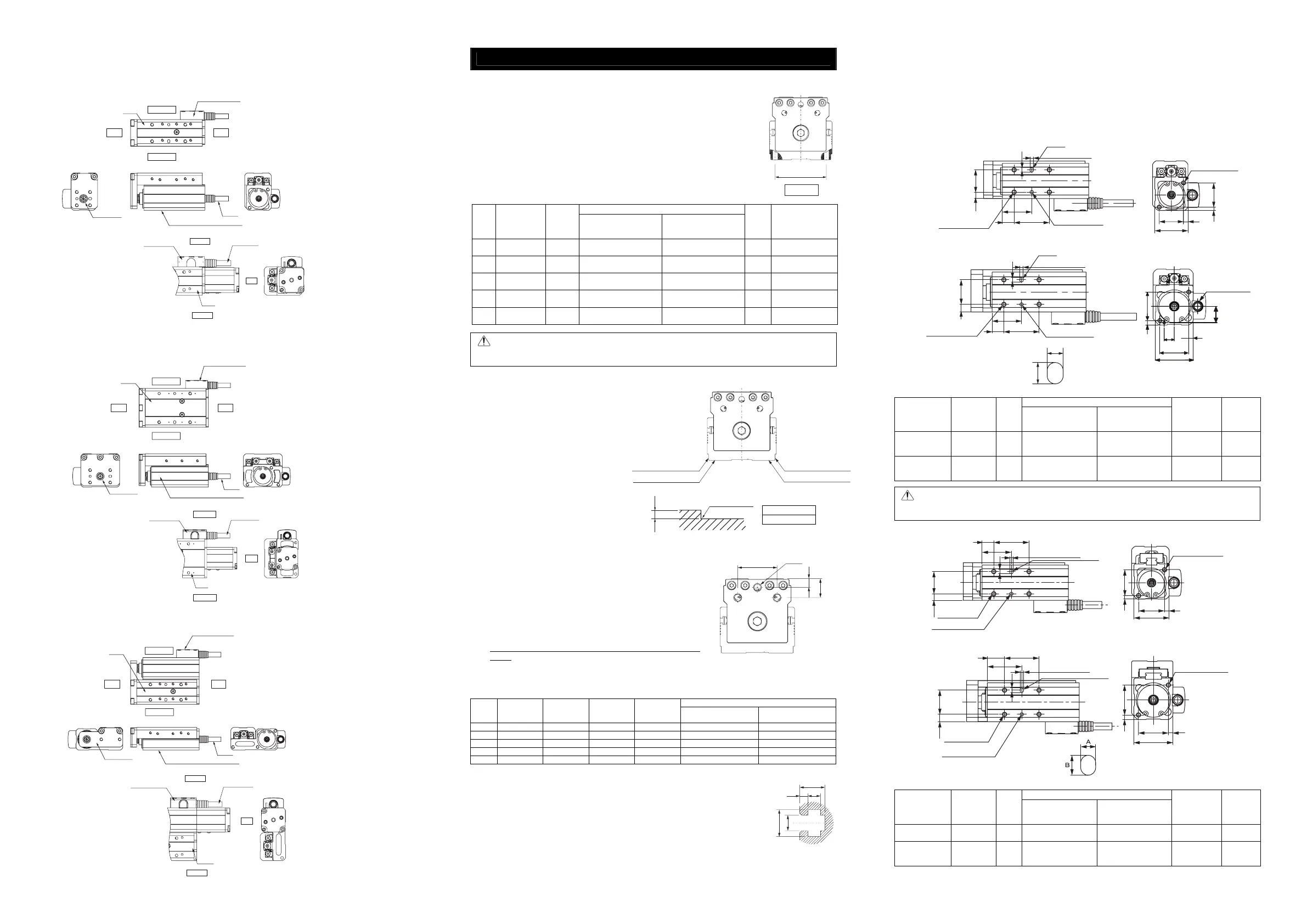
2. Total Length Short Type
2.1 Compact Type
RCA2-TCA3NA, TCA3N (Lead Screw, Ball Screw), TCA4NA, TCA4N (Lead Screw, Ball Screw)
• Without Brake
• Brake-equipped
2.2 Wide Type
RCA2-TWA3NA, TWA3N (Lead Screw, Ball Screw), TWA4NA, TWA4N (Lead Screw, Ball Screw)
• Without Brake
• Brake-equipped
2.3 Flat Type
RCA2-TFA3NA, TFA3N (Lead Screw, Ball Screw), TFA4NA, TFA4N (Lead Screw, Ball Screw)
• Without Brake
• Brake-equipped
Attachment
1. Motor Unit Type
RCP3-TA3C, TA4C, TA5C, TA6C, TA7C, TA3R, TA4R, TA5R, TA6R, TA7R
RCA2-TA4C, TA5C, TA6C, TA7C, TA4R, TA5R, TA6R, TA7R
1.1 Installing the Actuator
Fix it using the tapped hole on the rear side.
Description of the Set Screws
• For the base male set screw, use a hexagon socket head cap screw.
• For the bolt to be used, a high-tensile bolt complying with ISO-10.9 or more is
recommended.
• The length of thread engagement should be 1.8 times more than the nominal
diameter, and pay attention not to stick the screw out inside the actuator.
Tightening Torque
Model
Tap Size and
Max. Screw
Depth
Bolt to
be used
In the case that steel is
used for the bolt seating
surface:
In the case that aluminum
is used for the bolt seating
surface:
A(mm) Reamed Hole(mm)
TA3 M3 Depth 5 M3 1.54N·m(0.16kgf·m) 0.83N·m(0.085kgf·m) 28
Depth 3.5 from the
φ3H7 Base Surface
TA4 M4 Depth 7.5 M4 3.59N·m(0.37kgf·m) 1.76N·m(0.18kgf·m) 31
Depth 4.5 from the
φ4H7 Base Surface
TA5 M5 Depth 10 M5 7.27N·m(0.74kgf·m) 3.42N·m(0.35kgf·m) 45
Depth 5 from the
φ5H7 Base Surface
TA6 M5 Depth 10 M5 7.27N·m(0.74kgf·m) 3.42N·m(0.35kgf·m) 55
Depth 5 from the
φ5H7 Base Surface
TA7 M6 Depth 12 M6 12.34N·m(1.26kgf·m) 5.36N·m(0.55kgf·m) 64
Depth 6 from the
φ6H7 Base Surface
Note : Take care in selecting the bolt. Using a bolt with inappropriate length may cause damage to
the tapped hole, insufficient attachment strength of the actuator or interference with the
driving section, which may result in degradation of accuracy, damage or unexpected accident.
1.2 Attachment Surface
• The base has to have a structure with
sufficient rigidity to prevent oscillation.
• For the surface to which the actuator is
attached, a machined surface or flat one
with equivalent accuracy should be used.
The flatness should be within ±0.05mm/m.
• Secure the space where maintenance work
can be performed.
• This surface is used as the reference for the
actuator base side and lower side slider
running. In the case that the running
accuracy is required, attach the actuator
using this surface as the reference.
Refer to the following figure for the
processing when the actuator is attached to
the base using the base reference surface.
1.3 Attachment of the payload to be carried
• Fix the payload to be carried using the tapped hole on the front
plate or on the table upper surface.
• For the male set screw, use a hexagon socket head cap screw.
• For the bolt to be used, a high-tensile bolt complying with
ISO-10.9 or more is recommended.
• There are the two reamed holes on the upper surface of the table.
In the case that the reproducibility for the attachment and
removal is required, use these reamed holes. Also, in the case
that fine adjustment for squareness is required, select one of
these reamed holes to be used and adjust.
• Refer to the follow table for the screw depth and reamed hole
depth.
In the case that the screw is screwed in the hole to the depth more than the value in the following table, it
might cause a damage to the tapped hole or insufficient attachment strength of the object to be carried,
which may result in degradation of accuracy or unexpected accident.
Set Screw
Model A B C D
Screw Nominal
Diameter
Tightening Torque
TA3 24 5 10 M4 Depth 6 M4 1.76N·m(0.18kgf·m)
TA4 29 5 13 M5 Depth 6 M5 3.42N·m(0.35kgf·m)
TA5 29 6.5 14 M6 Depth 10 M6 5.36N·m(0.55kgf·m)
TA6 35 7 18 M6 Depth 13 M6 5.36N·m(0.55kgf·m)
TA7 44 6.5 21.5 M8 Depth 15 M8 11.48N·m(1.17kgf·m)
1.4 T-Groove
A T-groove is provided on the side of the main body of TA5C, 6C, 7C, 5R, 6R or 7R
to attach the external equipment (for M3). Use the groove freely for the sensor
attachment or fixing of wires, when necessary.
The dimensions of the groove are described as follows.
• For the nut used for the T-groove, a square nut is recommended, but a hexagon
nut can also be used.
• When it is attached, take care in selecting the bolt length so that the end of the
bolt does not touch the bottom section of the T-groove.
2. Total Length Short Type
2.1 Main Body Attachment
Fix it using the tapped hole on the rear side.
Description of the Set Screws
• For the base male set screw, use a hexagon socket head cap screw.
• For the bolt to be used, a high-tensile bolt complying with ISO-10.9 or more is recommended.
2.1.1 Compact Type
RCA2-TCA3NA, TCA3N (Lead Screw, Ball Screw), TCA4NA, TCA4N (Lead Screw, Ball Screw)
Tightening Torque
Model
Tap Size and
Max. Screw
Depth
Bolt to
be used
In the case that steel is
used for the bolt
seating surface:
In the case that
aluminum is used for the
bolt seating surface:
Slot
Reamed
Hole(mm)
TCA3NA, TCA3N
(Lead Screw,
Ball Screw)
M4 Depth 3 M4 3.59N·m(0.37kgf·m) 1.76N·m(0.18kgf·m)
A:3, B:4,
Depth: 3
φ3 Depth 3
TCA4NA, TCA4N
(Lead Screw,
Ball Screw)
M4 Depth 4 M4 3.59N·m(0.74kgf·m) 1.76N·m(0.35kgf·m)
A:3, B:4,
Depth: 3
φ3 Depth 3
Note : The tapped hole in the attachment section is partly a through hole. Never use the screw
longer than the screw effective length. Failure to do so may cause damage to inner
mechanism or electrical component.
Tightening Torque
Model
Tap Size and
Max. Screw
Depth
Bolt to
be used
In the case that steel is
used for the bolt
seating surface:
In the case that
aluminum is used for the
bolt seating surface:
Slot
Reamed
Hole(mm)
TC3N
(Lead Screw)
M4 Depth 3 M4 3.59N·m(0.37kgf·m) 1.76N·m(0.18kgf·m)
A:3, B:4,
Depth: 3
φ3 Depth 3
TC4N
(Lead Screw,
Ball Screw)
M4 Depth 4 M4 3.59N·m(0.74kgf·m) 1.76N·m(0.35kgf·m)
A:3, B:4,
Depth: 3
φ3 Depth 3
A
Table Type
A
B
C
3-D
5.5
1.8
5.8
3.3
2.7
A
R0.3 or less
Cable
Connector Cover
Main Body (Aluminum Frame)
Table
Right Side
Left Side
Front Plate
RearFront
Cable
Connector Cover
Main Body (Aluminum Frame)
Table
Right Side
Left Side
Front Plate
RearFront
Cable
Connector Cover
Main Body (Aluminum Frame)
Table
Right Side
Left Side
Front Plate
RearFront
Size A(mm)
2 to 4 or less
3 Depth 3
+0.05
0
Slot
2-M4 Depth 6
Tapped Hole
4-M4 Depth 4
Reamed Hole
195.5
4
10 30
25
30
22 4
223
(TC3N (Lead Screw) Ball Guide Type (Option: Model Code BG))
φ
3
Depth 3
+0.03
0
3 Depth 3
+0.05
0
26 4
34
4
4
6.5
21
30
15 30
Slot
Slot
2-M4 Depth 8
26
Tapped Hole
4-M4 Depth 5
Reamed Hole
(TC4N (Lead Screw), TC4N (Ball Screw) Ball Guide Type (Option: Model Code BG))
φ
3
Depth 3
+0.03
0
Actuator Cable
Connector Cover
Table
Right Side
Left Side
Rear
Connector Cover
Table
Actuator Cable
Right Side
Left Side
Rear
Table
Connector Cover
Right Side
Left Side
Rear
Actuator
Cable
Reamed Hole
Tapped Hole
4-M4 Depth 3
Slot
2-M4 Depth 6
22 4
30
22
3
4
19
5.5
3010
25
3 Depth 3
+0.05
0
+0.03
0
φ3 Depth 3
(TCA3NA, TCA3N (Lead Screw, Ball Screw))
Slot
A
B
4
216.5
25
10
30
Reamed Hole
Tapped Hole
4-M4 Depth 4
Slot
3 Depth 3
+0.05
0
3 Depth 3
+0.05
0
(TCA4NA, TCA4N (Lead Screw, Ball Screw))
2-M4, depth 8
4
26
14.9
26
9
4
34
 Loading...


