7
(2) ProfiBus-DP communication connector interface specifications
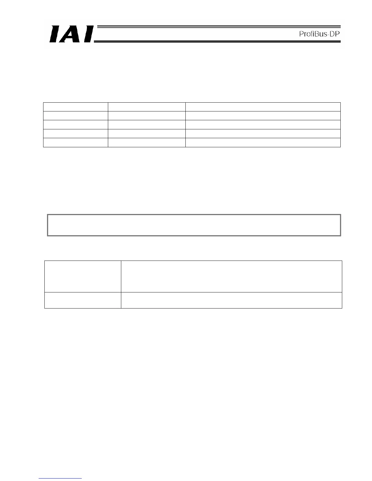
<Specifications of the ProfiBus-DP communication connector (1) A)>
This is a 9-pin, female D-sub connector recommended by the ProfiBus-DP standard EN 50170.
Connector
Pin No. Description Contents
3 B-Line RxD/TxD (Positive signal line)
5 GND Shield
8 A-Line /RxD x /TxD (Negative signal line)
Housing GND Shield
* Pins 1, 2, 4, 6, 7 and 9 are not used (they need not be wired).
(3) Bus termination settings <Set using the termination switch (1) B)>
Among the units connected to a ProfiBus-DP network, the devices at both ends require termination to prevent
reflected waves from entering the bus line again.
This ProfiBus-DP module provides a termination switch that makes this termination easy.
The user need not install a separate terminal resistor. Never install an additional terminal resistor, as it
may have negative impact on bus communication or cause a communication error, etc.
<Bus termination settings>
.
Termination switch ON Termination enabled
(If this switch is turned ON mistakenly when the module is connected in a position
other than the end of the network, bus communication may be negatively
impacted or a communication error, etc., may result.)
Termination switch OFF Termination disabled
 Loading...
