33
(7) Correspondence of RCS-C, E-Con and Scon I/O port numbers and PLC addresses
In the assignment of the RCS-C, E-Con or Scon’s ProfiBus-DP board I/Os in the input/output (memory) areas of
the PLC, one word of input/output area is occupied by 16 I/O points (dedicated inputs/outputs) of the slave
station.
The table below is an example of how I/O addresses are set when a RCS-C controller (eight dedicated input
points, 10 dedicated output points), E-Con controller (10 dedicated input points, 12 dedicated output points) and
Scon controller (16 dedicated input points, 16 dedicated output points) are connected as slave stations to the
master station.
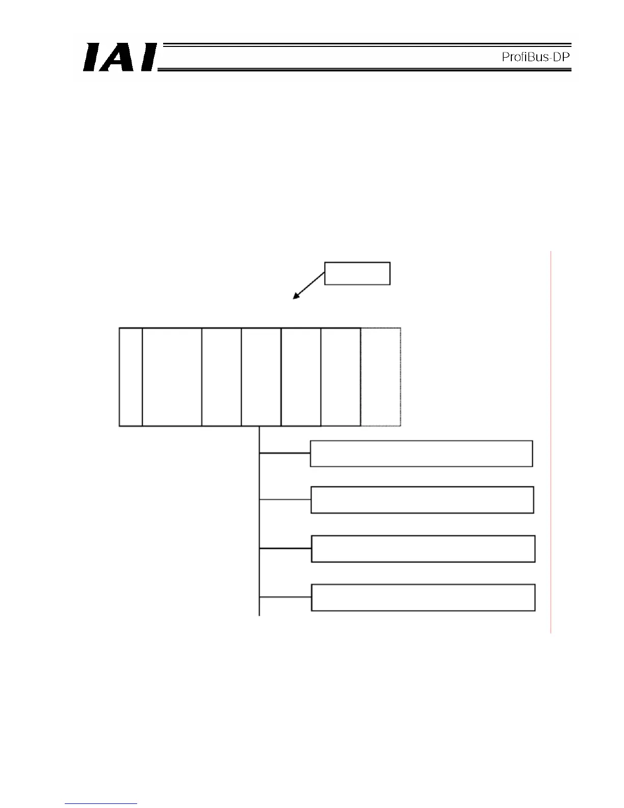
[1] Example of system configuration
An example of system configuration is shown below.
[2] Address assignment in the master station
When setting the configuration in [1] using a configurator, the numbers of inputs and outputs set for slave
station 2 must be set.
(Here, it is assumed that the number of occupiable slave stations is set to eight words in the PLC master
station.)
The respective I/Os are assigned addresses (bit addresses) as viewed from the PLC.
CPU
Bus station
number
Station 1 Station 2
Power supply
ProfiBus-DP
master station
Slave station 1
(RCS-C: Eight input points, 10 output points)
Slave station 2
(E-con: 10 input points, 13 output points)
Slave station 3
(SCon: 16 input points, 16 output points)
Slave station 4 (16 input points)
 Loading...
