26
4.2 Setting a ProfiBus-DP Board (Slave Station)
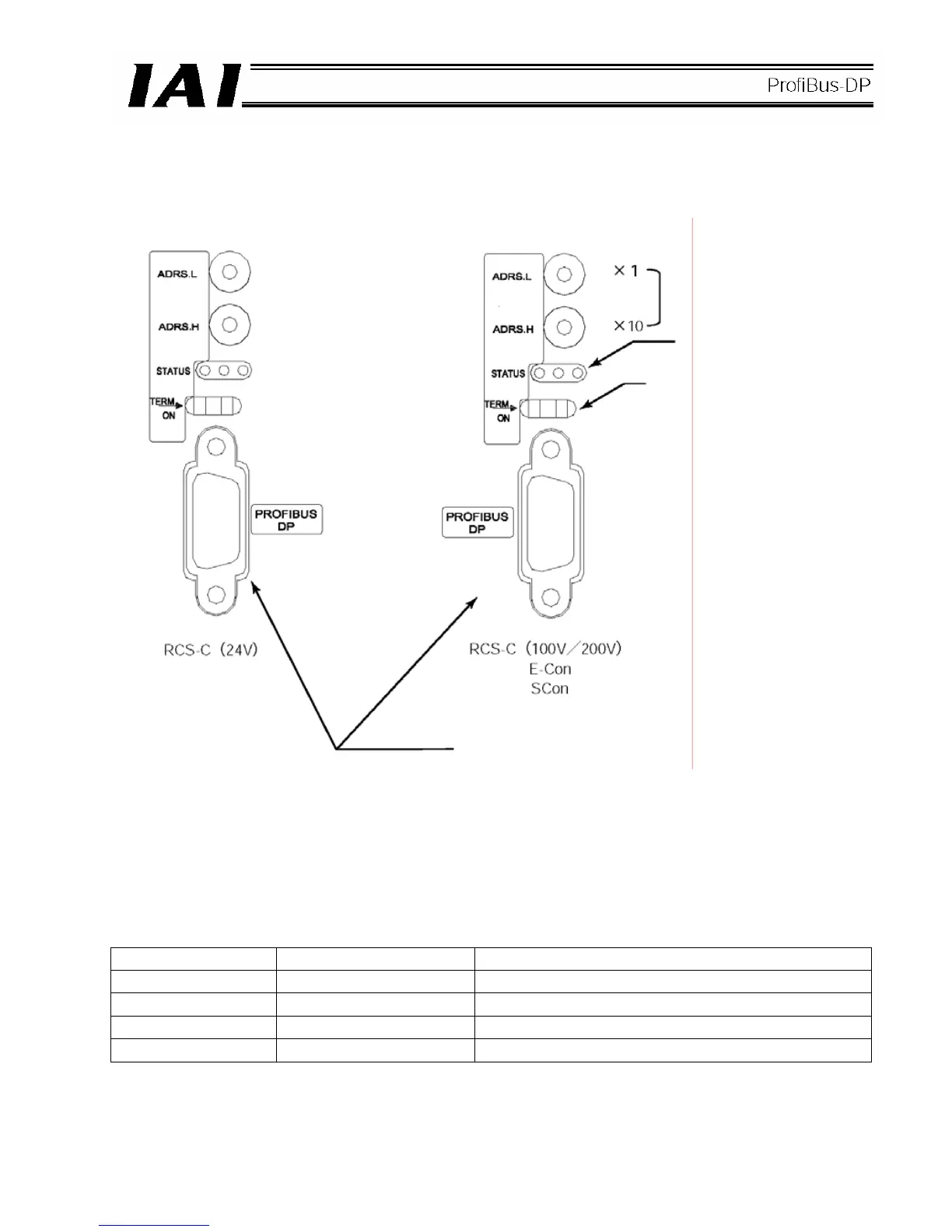
(1) Name of each part
(2) ProfiBus-DP communication connector interface specifications
<Specifications of the ProfiBus-DP communication connector (1) A)>
This is a 9-pin, female D-sub connector recommended by the ProfiBus-DP standard EN 50170.
Connector
Pin No. Description Contents
3 B-Line RxD/TxD (Positive signal line)
5 GND Shield
8 A-Line /RxD x /TxD (Negative signal line)
Housing GND Shield
* Pins 1, 2, 4, 6, 7 and 9 are not used (they need not be wired).
D) Address setting dials
C) Monitor LEDs
B) Termination switch
A) ProfiBus-DP communication connector
 Loading...
