29
(6) Input/output (I/O) signal assignments
The RCS-C, E-Con and Scon have the following numbers of inputs and outputs, respectively:
[1] RCS-C 8 dedicated input points, 11 dedicated output points (100/200-V specification) or 10 dedicated
output points (24-V specification)
[2] E-Con 10 dedicated input points, 13 dedicated output
[3] Scon 16 dedicated input points, 16 dedicated output
These inputs and outputs are assigned as shown below.
* For details on each signal, refer to “Operation Manual for RCS Series ROBO Cylinder Controller RCS-C Type,”
“Operation Manual for E-Con Controller” and “Operation Manual for Scon Controller.”
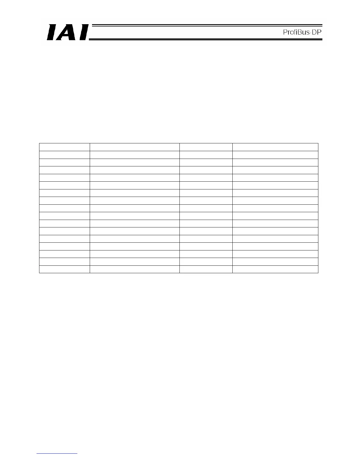
[1] RCS-C signal assignments
Input number Signal name Output number Signal name
0 Command position 1 0 Completed position 1
1 Command position 2 1 Completed position 2
2 Command position 4 2 Completed position 4
3 Command position 8 3 Completed position 8
4 Start 4 Positioning complete
5 Reset 5 Home return complete
6 Servo on 6 Zone
7 *Pause 7 *Alarm
8 Not used 8 *Emergency stop
9 Not used 9 Moving
10 Not used 10 *Battery alarm Note)
11 Not used 11 *Not used
12 Not used 12 *Not used
13 Not used 13 *Not used
14 Not used 14 *Not used
15 Not used 15 *Not used
Note) This signal is available only when the controller’s main power supply specification is 100/200 V.
 Loading...
