20
2) Address assignment in the master station
When setting the configuration in 1) using a configurator, the numbers of inputs and outputs of the X-SEL set
for slave station 2 must be determined. (Here, it is assumed that the number of occupiable slave stations is
set to 16 words in the master station.)
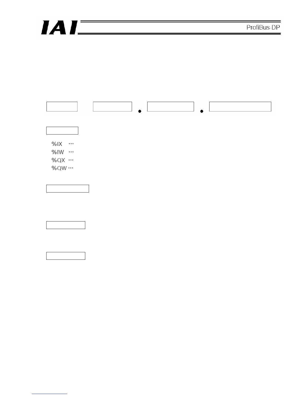
3) Bit address description
The inputs and outputs of the X-SEL are respectively assigned I/O addresses (word addresses) as viewed
from the PLC. The bit address description rules are specified below.
Prefix
Bus station number
This number indicates which of the units installed in the PLC is the ProfiBus-DP master unit. (Refer to the
figure in 1).)
Word number
A sequential number specifying a word when the I/Os assigned to the master station are arranged in words.
Bit address
A sequential number specifying a bit when the I/Os assigned within each word above are arranged in bits.
Prefix Word number Bit address
Bus station
number
Input bit address (address per bit)
Input word address (address per word)
Output bit address (address per bit)
Output word address (address per word)
 Loading...
