Manual ibaCom-L2B-x-8
10 Issue 3.2
5.1.2 7-Segment Display
The 7-segment display shows the following information:
Board ID (ranging from 0...3) - after board was initialized
The decimal point in the display indicates whether the
board is working as interrupt master / internal (dot is on) or
board is working as interrupt master / external (dot is blinking) or
board is working as interrupt slave (dot is off)
Note
External synchronization is not supported for PROFIBUS because it is not a synchro-
nized bus.
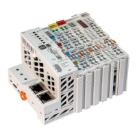
5.1.3 PROFIBUS Interface on ibaL2B-4-8
The ibaL2B-4-8-PCI connects the 4 L2B DP-slaves to one PROFIBUS DP-line.
5.1.4 PROFIBUS Interface on ibaL2B-8-8
The ibaL2B-8-8 connects the 2x4 L2B DP-slaves to two PROFIBUS DP-lines.
Upper PROFIBUS-connector “Channel A”
Lower PROFIBUS-connector “Channel B”
5.1.5 PROFIBUS Multimaster Mode
Each slave on the ibaL2B board can be assigned to be controlled by its individual mas-
ter. This means that on one DP bus several masters may be active, each controlling his
slave(s).
Note
It is not allowed to assign more that one master to a slave.
5.1.6 Activate / Deactivate PROFIBUS Bus Terminal Resistors
For each PROFIBUS line the line termination resistor can be activated or deactivated.
This allows the use of standard SUBD-9 connectors for connecting the PROFIBUS in-
stead using special connectors with included resistor termination networks.
You’ll find the switches for the termination resistors on the assembly side of the board
between front plate and piggy-back board.
Switch to the left side: Resistor off (disabled)
Switch to the right side: Resistor on (enabled)
Note
Please make sure, that the internal termination does not collide with an eventual exter-
nal termination (e. g. within the switch).