8.1.6 Link view – 32Mbit Flex
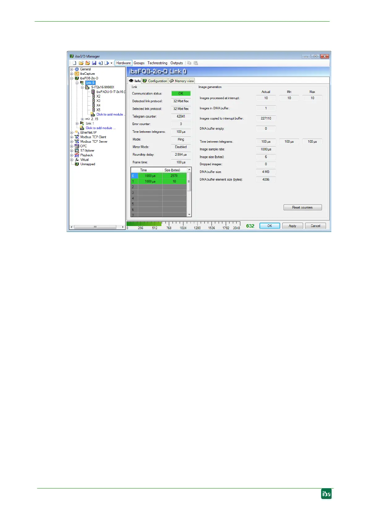
Figure 19: Link information at 32Mbit Flex
The screenshot above shows the information you see when the link is in 32Mbit Flex
mode. Up to 15 devices can be connected in a ring topology per link. In the signal tree
on the left side, the links 1 – 15 below the ibaFOB-D board correspond to the address
set by the rotary switch at the connected device.
Additional items, which are specific to 32Mbit Flex:
“Link” area
Time between telegrams
Time between two telegrams measured by the ibaFOB-D board. It should be equal
to the configured frame time.
Mode
Status of the connection mode
Ring: one or more devices (cascade) are bidirectionally connected and the FO ring
is closed.
Open chain: Only the fiber optic input is connected to a device. The output is not
connected or the FO ring is interrupted.
Mirror mode
Indicates whether morror mode is disabled or enabled. If mirror mode is enabled,
the display shows whether the board is configured as master or slave system. De-
scription of mirror mode see chapter 8.1.6.1.
Roundtrip delay
Telegram cycle in the closed FO ring. The time depends on the number of the con-
nected devices in the ring (approx. 2 µs per device).
Due to the roundtrip delay the data of the connected devices might be captured
asynchronously (up to one telegram cycle).
 Loading...