5.5 Front view
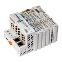
2 4 LEDs for link status
3 Fiber optic inputs
4 ID label of ibaFOB boards*
Figure 1: Front view
*This ID label is used to distinguish the individual ibaFOB board types. The following ID label
indicates the following board types:
D: ibaFOB-D and ibaFOB-Dexp
TDC:ibaFOB-TDC and ibaFOB-TDCexp
SD: ibaFOB-SD and ibaFOB-SDexp
PC: ibaFOB-PlusControl
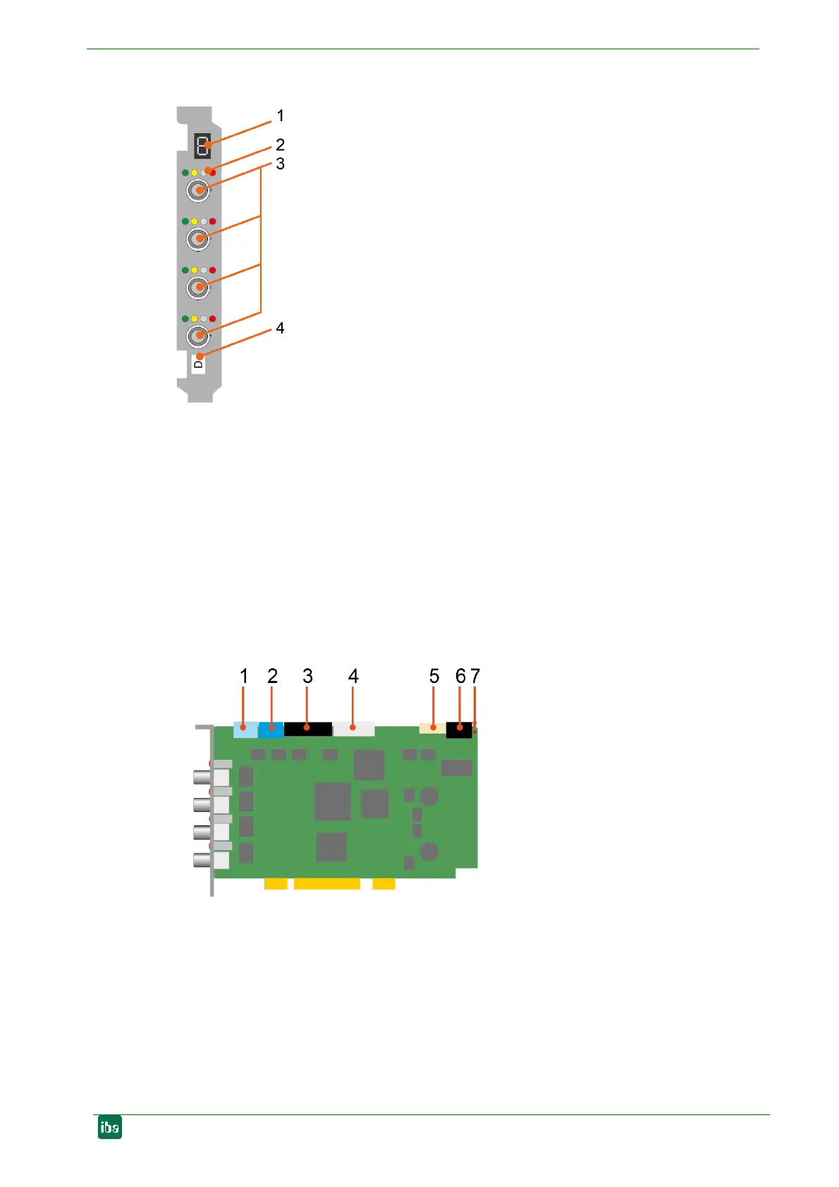
5.6 Additional board connectors
PCI boards
1
SYNC: synchronization of iba
boards (Sync-IRQ connector)
2 +5V: power supply for
Sync-i/Sync-o
3 TX-OUT: ibaFOB-4o-D
(outputs)
4 TX-MIRROR: ibaFOB-4o-D
(mirrored inputs)
5 JTAG: service interface
6 DCF77 & ALARM: spare con-
nector, prepared for future ex-
tensions
7 ALARM STATUS: debug LED
Figure 2: Additional board connectors, example ibaFOB-4i-D
 Loading...