INSTALLATIONS
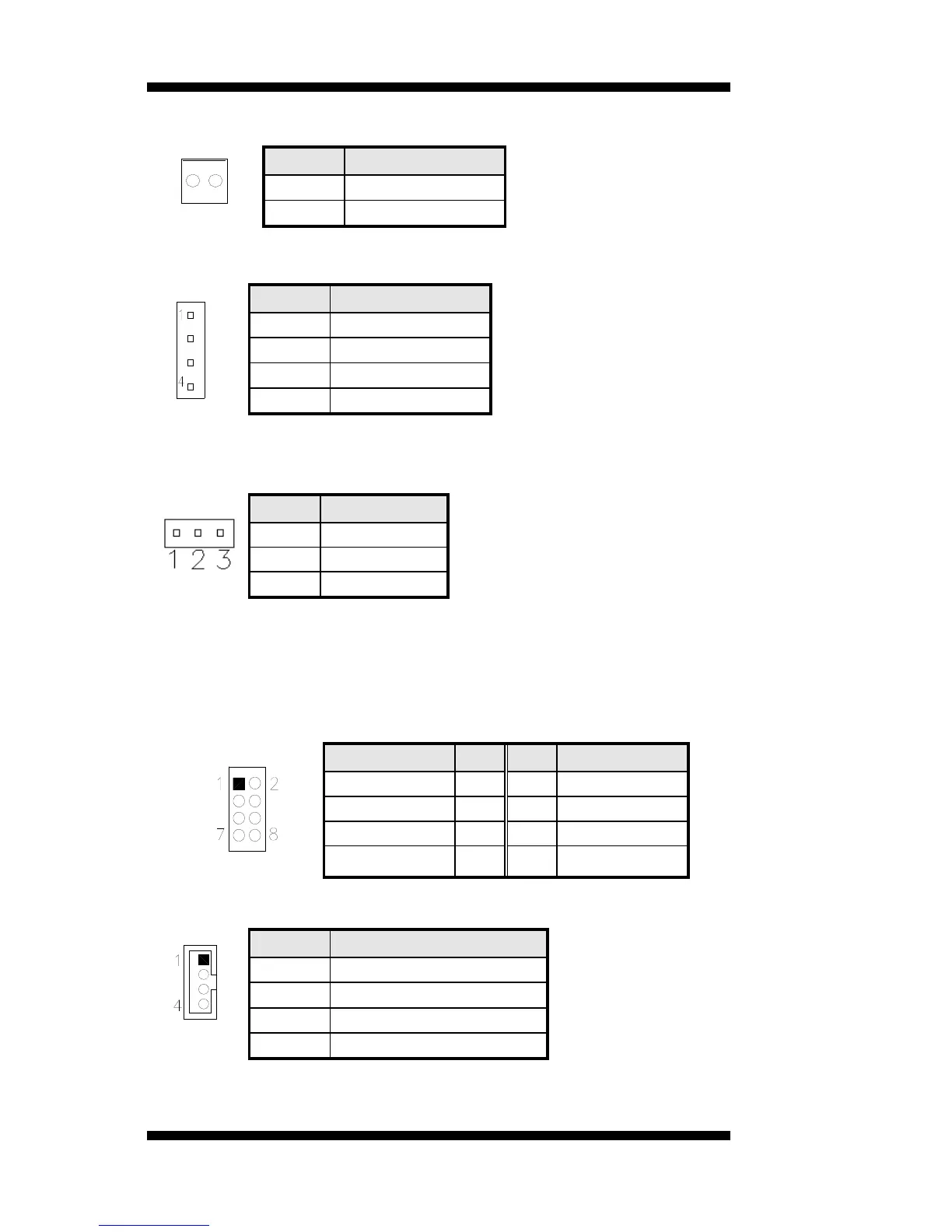
J1: Board Input Power Connector
1
Pin # Signal Name
1 +12V
2 GND
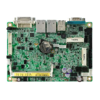
J2: HDD Power Connector (Output Only)
Pin # Signal Name
1 +5V
2 Ground
3 Ground
4 +12V
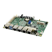
J3: Power LED
The power LED indicates the status of the main power switch.
Pin # Signal Name
1 Power LED
2 No connect
3 Ground
J4: Compact Flash Connector
J5: DDR2 SO-DIMM
J6, J7, J8: USB3/4/5/6/7/8 Connector
Signal Name Pin Pin Signal Name
Vcc 1 2 Ground
D- 3 4 D+
D+ 5 6 D-
Ground 7 8 Vcc
J9: LCD Backlight Connector
Pin # Signal Name
1 +12V
2 Backlight Enable
3 Brightness Control
4 Ground
14
IB891 User’s Manual