INSTALLATIONS
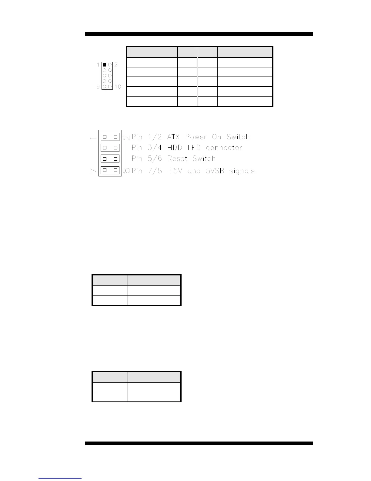
J10: Digital I/O
Signal Name Pin Pin Signal Name
GND 1 2 VCC
OUT3 3 4 OUT1
OUT2 5 6 OUT0
IN3 7 8 IN1
IN2 9 10 IN0
J11: System Function Connector
ATX Power ON Switch: Pins 1 and 2
This 2-pin connector is an “ATX Power Supply On/Off Switch” on the
system that connects to the power switch on the case. When pressed, the
power switch will force the system to power on. When pressed again, it
will force the system to power off.
Hard Disk Drive LED Connector: Pins 3 and 4
This connector connects to the hard drive activity LED on control panel.
This LED will flash when the HDD is being accessed.
Pin # Signal Name
4 HDD Active
3 5V
Reset Switch: Pins 5 and 6
The reset switch allows the user to reset the system without turning the
main power switch off and then on again. Orientation is not required
when making a connection to this header.
+5V and 5VSB Signals: Pins 7 and 8
Pin # Signal Name
7 +5V
8 +5VSB
IB891 User’s Manual 15
 Loading...