INSTALLATION AND OPERATION INSTRUCTIONS
1-18
SL 35-199, SL 45-260 MODULATING GAS BOILERS
System piping is connected to the boiler using the 1-1/2” NPT Male threaded
ttingsonthebottomconnectionports.Unionsandgateorballvalvesatthe
boilers supply and return water connections are recommended to simplify
servicing. Un-insulated hot water pipes must be installed with a minimum 1/4”
clearance from combustible materials.
Fluidllismostoftenaccomplishedbyusingaboilerregulator&llvalveset
at12psigormore,withappropriatebackowpreventiondeviceasrequired
by local code. This is acceptable in areas where municipal water or well water
hasbeentreatedandlteredtoremoveexcessivemineralsandsediment,and
water chemistry is known to be suitable for closed loop hydronic systems. In
areas where water quality is in question, or when chemical treatment or glycol is
required, other options should be considered. Follow applicable Codes and good
piping practice.
There are a number of boiler feed and pressurization devices on the market
todaythatmaybeabetterchoicethanarawwaterllfromthemains.When
regular maintenance requires relief valve blow-off, the discharge may be directed
backintothepressurizationunitforrecyclingofboileruidandchemicals
back into the system. In buildings that may be unoccupied for long periods of
time,pressurizationunitsareusefultopreventooddamageshouldleakage
occurfromanycomponentinthesystem.Anadditionalbenetisthatbackow
prevention devices are not required when using these devices.
Do not place any water connections overhead the boiler; leaks can damage
the fan & controls. If needed, create a shield over the top of the cover, but allow
clearanceforairowandserviceaccess.
For best results, use a Primary: Secondary piping system, with a pumped boiler
loop using 1-1/2” piping for the SL 35-199 and SL 45-260. Heat exchanger head
is only 2’ at 6 USgpm and approximately 13’ at 25 USgpm.
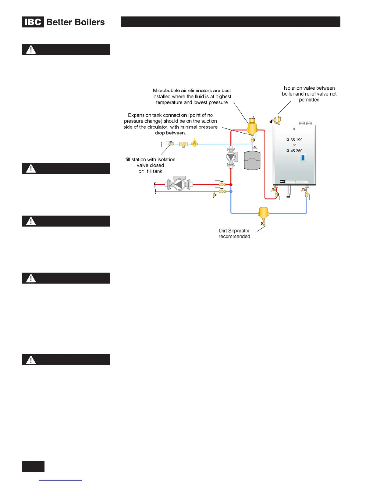
Figure 22: Boiler trim basic options - side piping
WARNING
Close ll valve after any
addition of water to the
system, to reduce risk of
water escapement.
CAUTION
Installers should inquire of
local water purveyors as to
the suitability of their supply
for use in hydronic heating
systems. If water quality is
questionable, a local water
treatment expert must
be consulted for testing,
assessment and, if required,
treatment. Alternatively, water
or hydronic uid of known
quality can be brought to the
site.
NOTE
Full sized application
drawings can be downloaded
from our web site.
www.ibcboiler.com
NOTE
The boiler, when used in
connection with a refrigeration
system, must be installed so
the chilled medium is piped
in parallel with the boiler with
appropriate valves to prevent
the chilled medium from
entering the boiler.
NOTE
The boiler piping system of
a hot water boiler connected
to heating coils located in
air handling units where
they may be exposed to
refrigerated air circulation
must be equipped with
ow control valves or other
automatic means to prevent
gravity circulation of the
boiler water during the
cooling cycle.

 Loading...


