INSTALLATION AND OPERATION INSTRUCTIONS
3-2
SL 35-199, SL 45-260 MODULATING GAS BOILERS
3.2 PRIOR TO START-UP
3.2.1 Pre-Ignition Checks
1. Ensureventingsystemiscompleteandsealtested.Conrmanycommon
venting system at the installation site is isolated and independent of the SL
boiler, that any holes left from removal of a previous boiler have been sealed,
andthatanyresizingoftheolduehasbeendone.Fillcondensationtrap.
2. Checkwaterpipingsystemisfullyushedandcharged,andthatallair
has been discharged through loosened bleed caps. Note it is possible to
switch all pumps on/off from the Touch Screen – without a call for heat.
Thisgreatlysimpliessystemllingandairbleeding(gotoInstaller Setup,
System Settings, Site Settings, change Manual Pump Purge to “ON”. When
complete, return to Off, or this will automatically occur with a call for heat).
Useaminimumwaterpressureof12psig.Andconrmpressurereliefvalve
is installed and safely drained.
3. Check to see that adequate gas pressure is present at the inlet gas supply
testport.Openthetestport(usingasmall(1/8”or3mm)atscrewdriver,
open the test port by turning its center-screw 1 full turn counterclockwise.
Connect a manometer and open the gas control valve. Requirements are
minimum 5” w.c and maximum 14” w.c. Check to ensure no gas leaks.
4. Performanalcheckofelectricalwiringandprovidepowertotheboilerto
initialize operation.
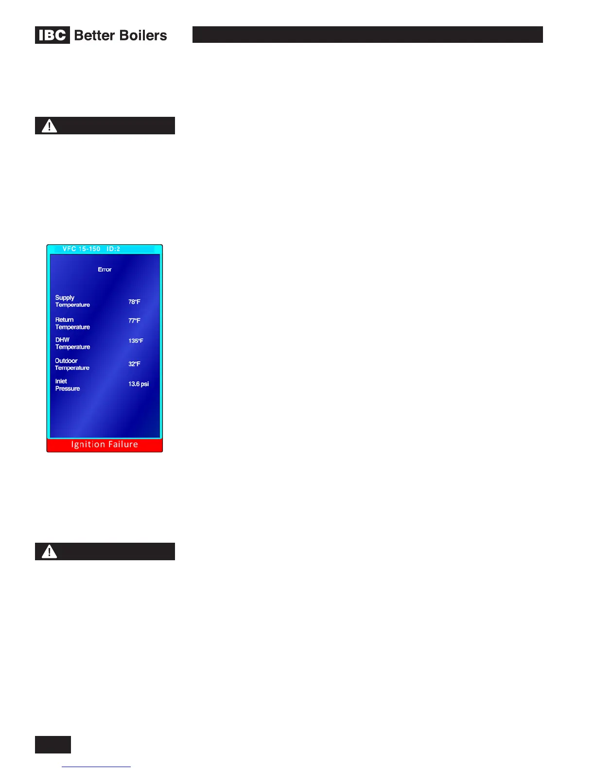
3.2.2 Test Ignition Safety Shutoff
With the boiler in operation, test the ignition system safety shutoff device by
shutting the gas control valve immediately outside the boiler case. Ensure boiler
has shut off and the appropriate Error information is displayed on the Touch
Screen. To restart boiler, reset power or press “Clear Errors” in the Advanced
Diagnostics section.
COMMISSIONING
The SL 35-199 and SL 45-260 boilers use different gas valves. Although the gas
valves are different, the operation and adjustment is the same. The test ports
and the adjustment ports are however in different positions. See page 3-4 for
photographs identifying the test and adjustment ports on each of the 2 valves.
The SL 35-199 and SL 45-260 modulating boilers are factory calibrated to
operate with natural gas (or propane if so ordered) at sea level. The Low
Fire (Zero Offset) valve adjustment cap has been factory sealed using paint-
seal compound. This cap must not be tampered with. The Low Fire (Zero
Offset) screw is not to be adjusted in the eld. The High Fire (Gas:Air ratio)
adjustment screw may have to be adjusted to attain optimum combustion results
if required, however, no mixture adjustment shall be performed unless
done by a qualied technician using properly functioning and calibrated
combustion analyzing equipment.
The controller will automatically detect the installations altitude and make the
appropriate adjustments to operate the boiler up to 4,500 feet in elevation without
3.3
DANGER
Making adjustments to
the IBC gas valve without
a properly calibrated gas
combustion analyzer and by
persons who are not trained
and experienced in its use
is forbidden. Failure to use
an analyzer can result in an
immediate hazard.
WARNING
Fill trap with water before
boiler is rst red to prevent
exhaust fumes from entering
room. Never operate the
boiler unless the trap is lled
with water. Failure to comply
will result in severe personal
injury or death.
Error displayed after testing ignition
safety shut off

 Loading...


