INSTALLATION AND OPERATION INSTRUCTIONS
5-8
SL 35-199, SL 45-260 MODULATING GAS BOILERS
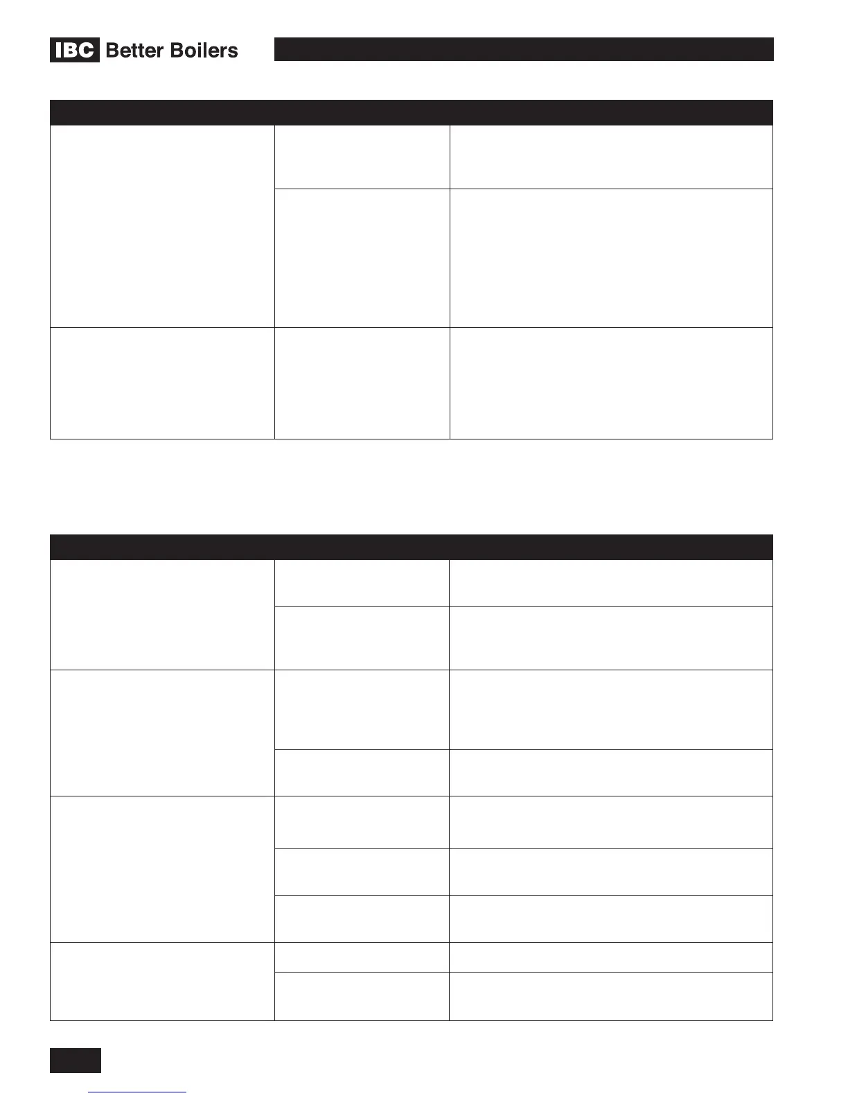
SYMPTOM DIAGNOSIS REMEDY
TEMPERATURE SENSOR
ERROR
Touch Screen Message:
Error - Max. Inlet/Outlet Sensor
Temp. Exceeded. -> Check
water ow
Water temperature signal
not within acceptable range.
Potential ow or sensor failure.
Consult service technician.
Current outlet
temperature exceeds
operating limit.
• Checkwaterow.
Defective or
disconnected
temperature sensor.
• Check wiring to temperature sensor and
control module.
• Check temperature sensor. See Section
5.2.1.
MISCELLANEOUS
Touch Screen Message :
Blank – screen dark, but fan
running Indicative of power-
surge damage to appliance
• Check transformer; replace if damaged.
• Check circuit board for visible damage.
5.3.2 Ignition Problems
SYMPTOM DIAGNOSIS REMEDY
NOISY SPARK WHEN
IGNITING
Ignition lead is not
rmly connected.
Reconnect ignition lead.
Contaminants/
moisture on igniter
probe/ame sensor.
Ensure probe is dry by re-running post-purge;
otherwise, clean or replace igniter probe.
BOILER RUMBLES WHEN
IGNITING.
Fluctuating gas
pressure/ gas
pressure too high/too
low.
Check CO
2
level via analyzer.
Check for proper gas
piping.
Check pressure with manometer during ignition.
BOILER WILL NOT ATTEMPT
TO IGNITE. FAN AND PUMP
ARE OPERATING NORMALLY.
No power to ignition
control module.
• Check system wiring.
• Check air reference tubing.
Igniter probe/ame
sensor disconnected.
Reconnect probe.
Defective Control
Module.
Check ignition output from control module.
BOILER WILL NOT ATTEMPT
TO IGNITE. FAN AND / OR
PUMP ARE OFF DISPLAY
NOT ILLUMINATED
No power to boiler. Check line voltage .
Defective transformer. Check transformer. Reconnect or replace as
needed.