1-1
INSTALLATION
SL 35-199, SL 45-260 MODULATING GAS BOILERS
INSTALLATION1.0
GENERAL
SLSeriesgas-redmodulatingboilersarelowpressure,fullycondensingunits
having variable input ranges (see specication chart - inside, front cover). The
boilers are approved as “Category IV” vented appliances using either Direct
Vent (sealed combustion) or indoor combustion air, providing a great degree of
installationexibility.
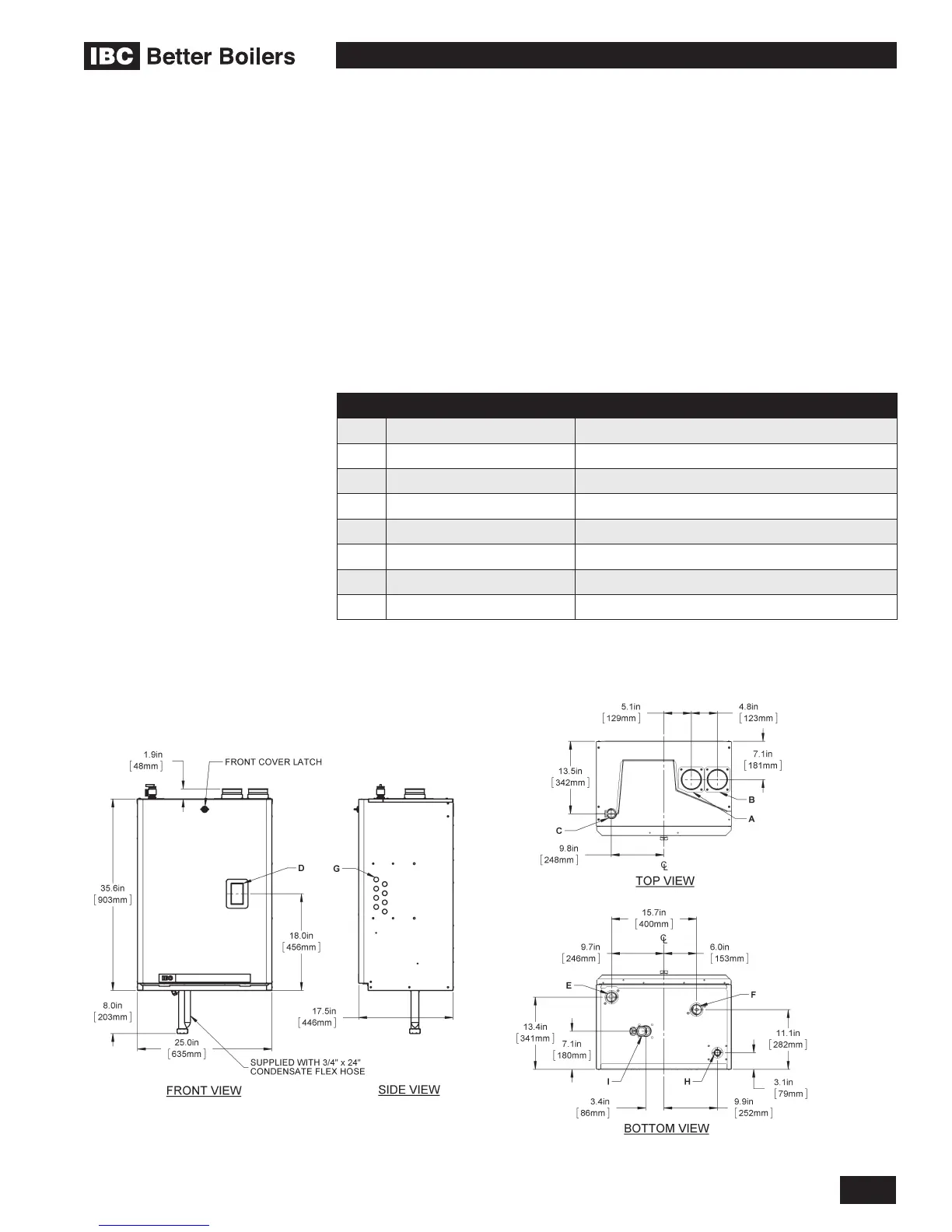
Figure 1 shows outer case dimensions and piping and electrical holes. Use this
diagramtondasuitablelocationfortheboiler.See also Section 1.3 Location.
DESCRIPTION SL 35-199, SL 45-260
A Exhaust Outlet 3” Schedule 40
B Combustion Air 3” Schedule 40
C Touch Screen Display 2-1/4” x 4”
D Water Outlet 1-1/2” NPT-M
E Water Inlet 1-1/2” NPT-M
F Knock-outs (8) 1/2”
G Gas Inlet 3/4” NPT-F
H Condensate Outlet 3/4” Hose
Table 1: Connections
1.1
Figure 1a: Dimensions / Connections for SL 35-199, SL 45-260 Figure 1b: Dimensions / Connections for SL 35-199, SL 45-260