INSTALLATION AND OPERATION INSTRUCTIONS
4-4
SL 35-199, SL 45-260 MODULATING GAS BOILERS
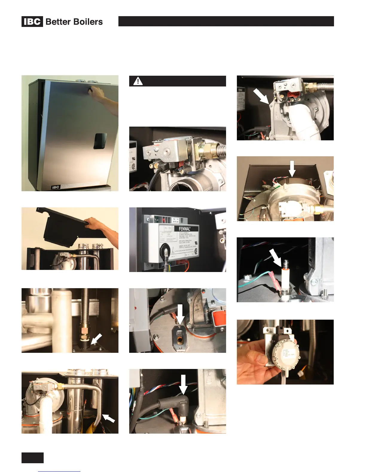
Removing top service cover
Removing front cover
Gas inlet connection on side
Gas valve
Gas supply line
Ignition wire boot
Fan housing
Fan pressure sensor
Fan motor
Ignition module
Sight glass (burner observation port)
GEOGRAPHY & COMPONENTS4.2
NOTE
Vent stack piping and air intake
riser have been removed in some
of these photos for clarity
Ignition electrode/ame sensor

 Loading...


